Week-7 Head Impact
AIM: To replicate a scenario where headform will impact on a car bonnet. The meshed hood model with elasto-plastic material card has to be used as the bonnet. From the simulation, the head impact coefficient must be calculated manually and with the help of LS-PrePost.
DELIVERAEBLES:
- The impact simulation of a simple head impact with the Rigid wall.
- The impact simulation of the Headform provided with the Rigid wall with the Stress / Strain plots and acceleration plot.
- The impact simulation of the head form with the Hood with the Stress / Strain plots and acceleration plot. For the hood, you can use Aluminium.
- The Stress / Strain plot from the Rigidwall simulation should be compared with the Stress / Strain plot from the Hood Simulation and there should be a detailed explanation if there is any difference in the plots.
PROCESS:
- To replicate the real impact situation transformation of the original geometry is necessary. DEFINE_TRANSFORMATION card is used to rotate the original body about Y-axis.
- INCLUDE_TRANSFORM card is necessary to complete the rotation procedure. In this card, the original geometry is called through filename and defined transformation is carried out on that geometry. Transformation ID(TRANID) is set accordingly for this card. A separate keyword file is created with these keywords. The original input file is not changed but only called for transformation. Further required keywords are added in this NEW input file. Both the keyword files the original input file and the new (transformed) input file are kept in the same folder.
- Close and open the NEW MAIN file to see if the changes made are reflected in the model.
*******IMPORTANT: WHILE CREATING ANY NEW KEYWORDS OR CHANGING THE KEYWORDS USED FOR THESE KIND OF MODELS IT IS NECESSARY TO SAVE CHANGES IN MAIN FILE TO AVOID MODIFICATION TO OTHER FILE IN PRESENT IN THE SUBSSYTEMS. ALWAYS CHECK FOR THE FILE IN WHICH YOU ARE SAVING THE MODEL/PROJECT OR WHILE CREATION OF ANY NEW KEYWORD*******
- CONSTRAINED_EXTRA_NODE_SET:
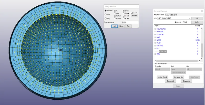
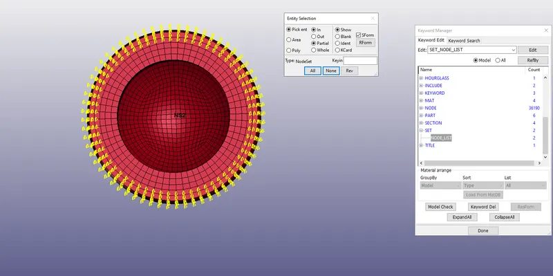
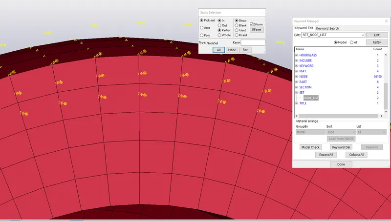
- One CENS is defined under PEDESTRIAN_HEADFORM.k file between a PART and NODE SET. PID is for Skull and NSID is defined for nodes on inner 3 layers of Skin part. You can clearly notice the penetration between Skull and Skin parts as shown.
- Extra nodes for rigid bodies may be placed anywhere, even outside the body, and they are assumed to be part of the rigid body. They have many uses including:
1. The definition of draw beads in metal forming applications by listing nodes along the draw bead.
2. Placing nodes where joints will be attached between rigid bodies.
3. Defining a node where point loads are to be applied or where springs may be attached.
4. Defining a lumped mass at a particular location. - The contact algorithm checks for penetration at the integration points. Integration points are equally spaced along the draw bead and do not depend on the nodal spacing used in the definition of the draw bead. By tying extra nodes to rigid bodies (see *CONSTRAINED_EXTRA_NODES or *CONSTRAINED_RIGID_BODIES), the draw bead nodal points do not need to belong to the element connectivities of the die and binder. The blank makes up the master surface.
**REMARKS WHY NOT CONSTRAINED NODE SET
1. Since no rotation is permitted, this option should not be used to model rigid body behavior involving rotations.
2. Mass- The masses of the nodes are summed up to determine the total mass of the constrained set.
3. Nodal Rigid Body- Note that the definition of a nodal rigid body is not possible with this input. For nodal rigid bodies the keyword input *CONSTRAINED_NODAL_RIGID_BODY_OPTION must be used.
4. Failure Time. When the failure time, TF, is reached the nodal constraint becomes inactive, and the constrained nodes may move freely.
- CONSTRAINED_RIGID BODIES:
- Two contrained RIGID_BODIES are defined under PEDESTRIAN_HEADFORM.k model. One is between Acceleration blocka s slave and Skull as Master. Another is between Back plate as Slave and Skull as Master
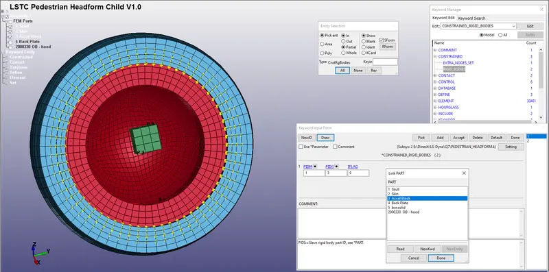
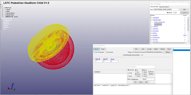
- The purpose of *CONSTRAINED_RIGID_BODIES is to merge two rigid bodies. One rigid body, called the constrained rigid body, is merged into another one, called the lead rigid body. This command applies to parts comprised of *MAT_RIGID but not to nodal rigid bodies (*CONSTRAINED_NODAL_-RIGID_BODY).
1. Inertial Properties. The constrained rigid body is merged to the lead rigid body. Unless the inertial properties of the lead rigid body are defined with *PART_INERTIA, the inertial properties computed by LS-DYNA are based on the combination of the lead rigid body plus all the rigid bodies which are constrained to it. If the inertial properties of the lead are specified with *PART_-INERTIA, then the treatment of those properties depends on IFLAG. Note that a lead rigid body may have many rigid bodies constrained to it, but it may not be constrained to another rigid body.
2. Common Nodes. Independent rigid bodies must not share common nodes since each rigid body updates the motion of its nodes independently of the other rigid bodies. If common nodes exist between rigid bodies, the rigid bodies sharing the nodes must be merged.
3. Completely Separated Rigid Bodies. Completely separated rigid bodies that do not share any common nodal points or boundaries may also be merged. All actions valid for the lead rigid body, such as constraints and given velocity, are
now also valid for the newly-created rigid body.
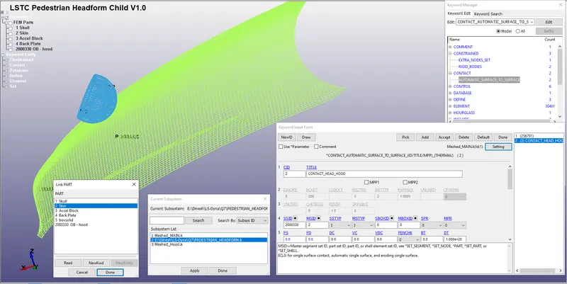
- CONTACT_AUTOMATIC_SURFACE_TO_SURFACE:
- One ASTS contact is defined under PEDESTRIAN_HEADFORM.k model between two parts with skull as slave and skin as master.
- Another ASTS is added to the list under MAIN.k file model between two parts the bonnet slave and the skin as Master.
Head injury criteria (HIC)
Hheadfoam impactors are used to test the behavior of vehicle structures such as the hood. In a pedestrian-vehicle impact, the kinematics and severity of pedestrian injuries are affected by the impact locations on the vehicle and body velocities after impact. The objective of this project is to analyze the pedestrian kinematics in a Pedestrian-Car accident scenario and determine the Head Injury Criteria (HIC) from the head resultant acceleration, for head impacts on the vehicle hood
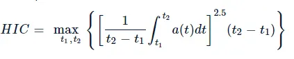
The equation that used for the measurements of the head injury of the whole model for the pedestrian head impact was head injury criteria (HIC). It has been used to predict the risk of engine hood to a pedestrian during the collision
HIC is calculated according to the below Equation

Where
- a: the resultant acceleration (as a multiple of 10 ms-2 or about 1 g
- t1, t2: two-time instants (in seconds), which define the start and end of the recording when HIC is at maximum. Values of HIC at the time interval t1-t2
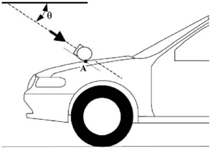
The test setup as per AIS 100.
The release angle is 50⁰ for the child headfoam. The headfoam velocity at impact is 11.1mm/ms (40 km/h). Impact point on the Rigidwall instead of car hood in this case.
- CONTROL_ACCURACY, CONTROL_BULK_VISCOSITY, CONTROL_CONTACT, CONTROL_ENERGY, CONTROL_OUTPUT, CONTROL_UNIT
- CONTROL_ACCURACY: Purpose: Define control parameters that can improve the accuracy of the calculation.
Remarks:
1. Second Order Objective Stress Update.
Second order objective stress updates are occasionally necessary. Some examples include spinning bodies such as turbine blades in a jet engine, high velocity impacts generating large strains in a few time steps, and large time step sizes due to mass scaling in metal forming. There is a significantly added cost which is due in part to the added cost of the second order terms in the stress update when the Jaumann rate is used and the need to compute the strain-displacement matrix at the mid-point geometry. This option is available for the following element types:
a) one point brick elements
b) the selective-reduced integrated brick element which uses eight integration points
c) fully integrated plane strain and axisymmetric volume weighted (type 15)
2D solid elements
d) the thick shell elements
e) Belytschko-Tsay shell elements
f) Belytschko-Tsay shell elements with warping stiffness
g) Belytschko-Chiang-Wong shell elements
h) S/R Hughes-Liu shell elements
i) type 16 fully integrated shell element
2. Invariant Node Numbering for Shell Elements. Invariant node numbering
for shell and thick shell elements affects the choice of the local element shell
- CONTROL_BULK_VISCOSITY: Purpose: Reset the default values of the bulk viscosity coefficients globally. This may
be advisable for shock wave propagation and some materials. Bulk viscosity is used to treat shock waves. A viscous term, q, is added to the pressure to smear the shock discontinuities into rapidly varying but continuous transition regions. With this method the solution is unperturbed away from a shock, the Hugoniot jump conditions remain valid across the shock transition, and shocks are treated automatically.
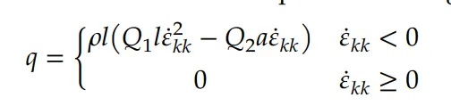
where Q1 and Q2 are dimensionless input constants which default to 1.5 and 0.06, respectively, l is a characteristic length given as the square root of the area in two dimensions and as the cube root of the volume in three, and a is the local sound speed. See Chapter 21 in the LS-DYNA Theory Manual for more details. The Richards-Wilkins, see [Richards 1965, Wilkins 1976], bulk viscosity considers the directional properties of the shock wave which has the effect of turning off the bulk
viscosity in converging geometries minimizing the effects of “q-heating.” The standard bulk viscosity is active whenever the volumetric strain rate is undergoing compression even though no shock waves are present.
- CONTROL_CONTACT: Purpose is to Change defaults for computation with contact surfaces.
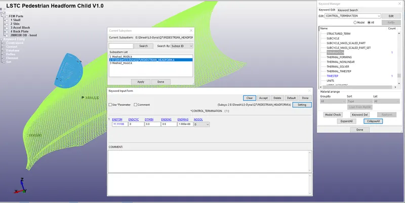
Results :
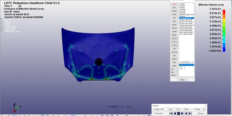
Effective stress values for Hood : Max Effective Stress: 73.4 MPa
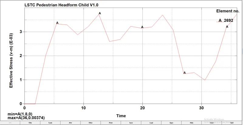
Effective stress values for Head : Max Effective Stress: 3.74 MPa
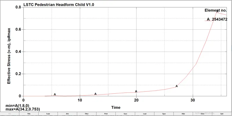
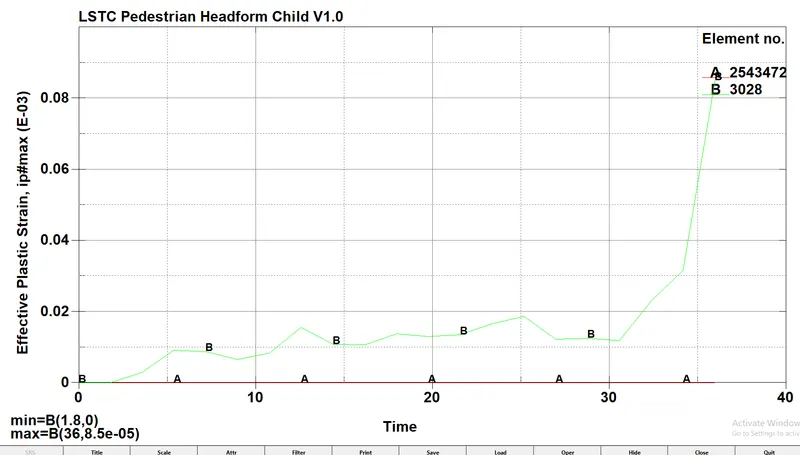
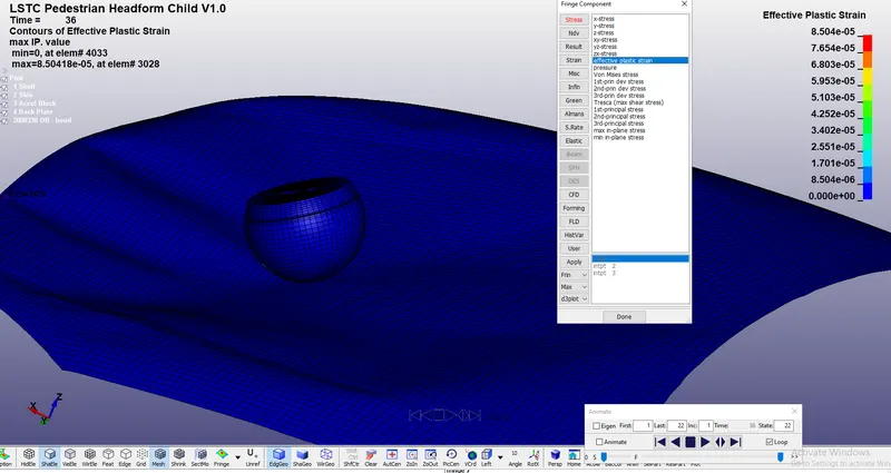
Effective Plastic strain values: Max Effective Plastic Strain: 0.085
In this case, the hood was defined with a elastic material model for Aluminium-shell elements which is a deformable model so during the impact the hood deforms significantly and reduces stress and strain on the head foam. The effective plastic strain showed on the graph is for the hood components because there was no deformation in the head model.
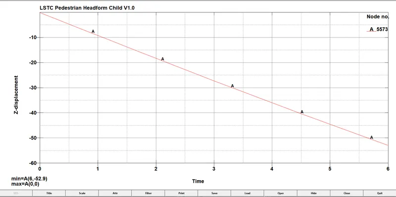
Displacement of Hood: Max Displacement on the area of contact: 53 mm
Head injury criteria (HIC):
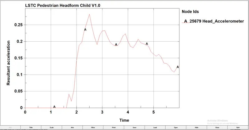
HIC: 393.1 and HIC(d): 463 Which is less than the Protocol Standard HIC value 650
The HIC-36 value for headfoam impact is measured from an accelerometer place in the geometry. From the graph it can be seen, the resultant acceleration is increased and during the initial impact stage decreased after the 26 ms because the hood deforms gradually and slows down the head velocity.
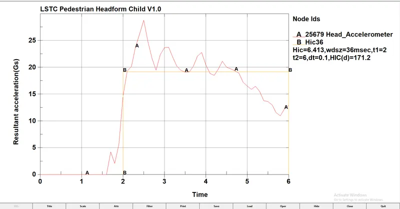
The HIC36 value obtained from LS-PrePost for this case is 6.413 and HIC(d) value is 171.1 which is less than the safe HIC value of 650 as per Euro NCAP Protocol because the hood absorbs the impact energy and gets deformed.
Manual calculation of HIC value:
The expression to calculate HIC value is,
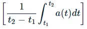
The average value of acceleration for the time interval of t1= 2 ms and t2=6 ms is,
The HIC36 value obtained from LS-PrePost for this case is 6.413 and HIC(d) value is 171.1 which is less than the safe HIC value of 650 as per Euro NCAP Protocol because the hood absorbs the impact energy and gets deformed.