Week-7 Head Impact
Week-7
- The impact simulation of a simple head impact with the Rigid wall.
- The impact simulation of the Headform provided with the Rigid wall with the Stress / Strain plots and acceleration plot.
- The impact simulation of the head form with the Hood with the Stress / Strain plots and acceleration plot. For the hood, you can use Aluminium.
- The Stress / Strain plot from the Rigidwall simulation should be compared with the Stress / Strain plot from the Hood Simulation and there should be a detailed explanation if there is any difference in the plots.
Case-1: (Headform provided with the Rigid wall)
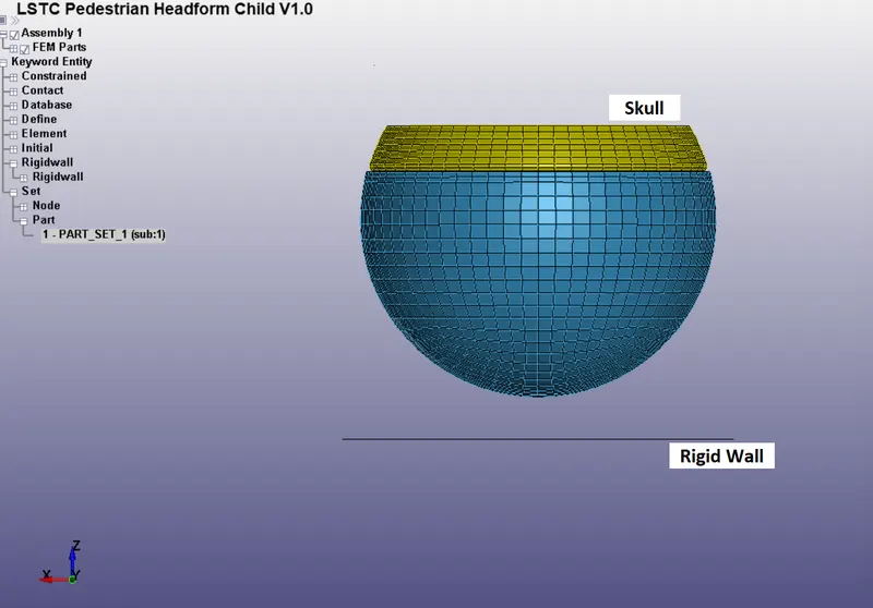
- The first step is to open the headform model in a new file and create a rigid wall below the skull.
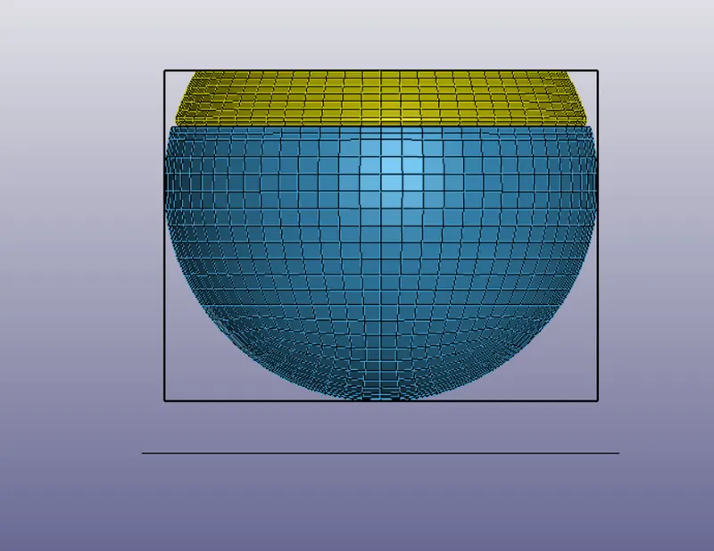
- Then the next step is to create box for the whole headform to define initial velocity to the head.
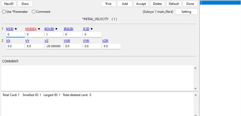
- The next step is to define the initial velocity in using Initial_Velocity card.
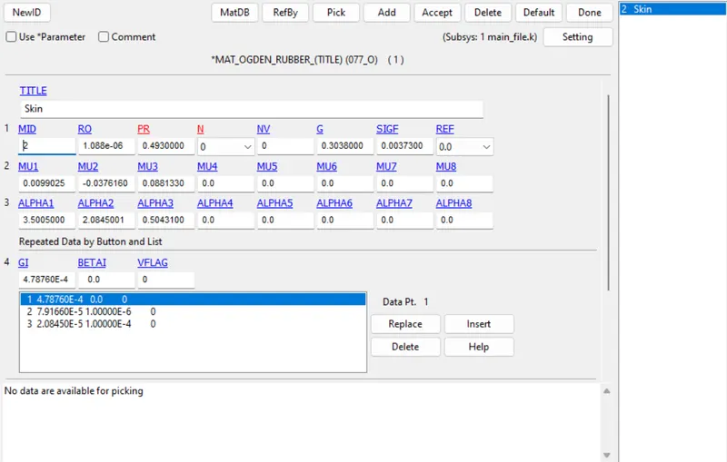
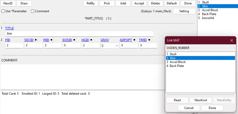
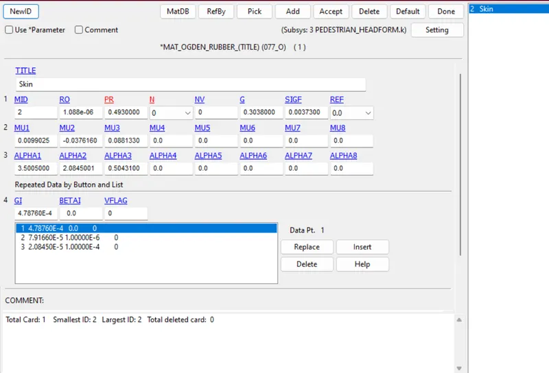
- The next step is to define material for skin of skull using the Ogden model and rubber as material property.
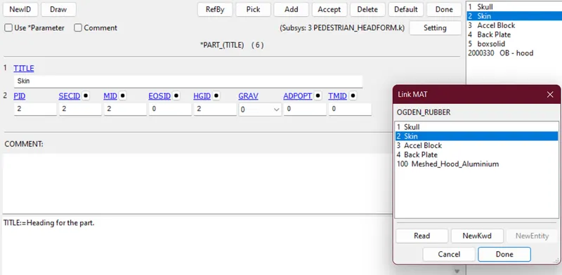
- Then the next step is to define the material card in the respective part in order to assign the material property.
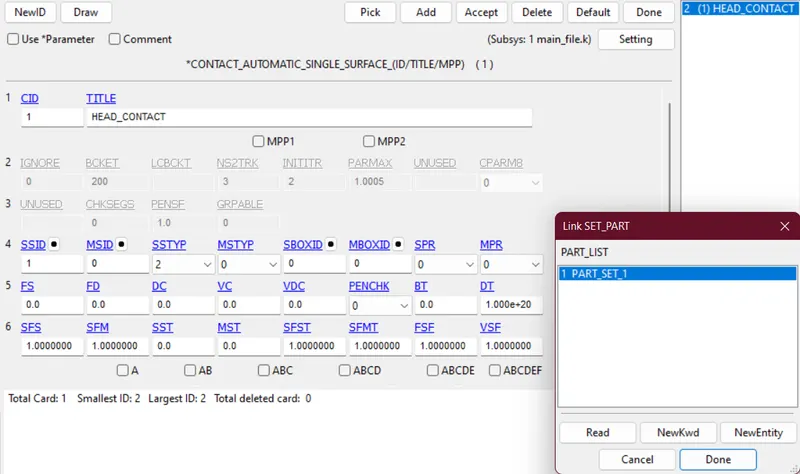
- The next step is to define contact as there are two types of contact one is Automatic_single_surface and other one is Automatic_surface_to_surface.
- Automatic_single_surface is used to model the contact between skin and rigid wall.
- Slave Segment-
- Slave Segment-
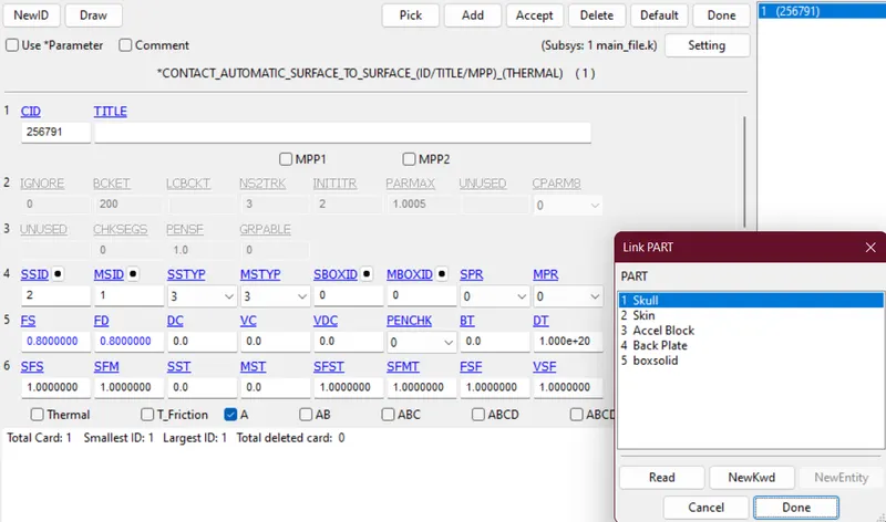
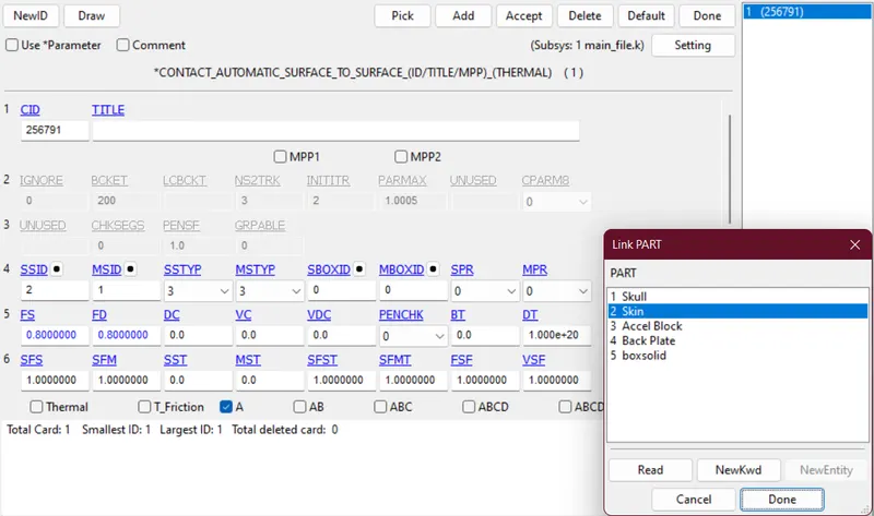
- Automatic_surface_to_surface is used to model the contact between head skin and skull.
- Master Segment-
- Slave Segment-
- Master Segment-
- Automatic_single_surface is used to model the contact between skin and rigid wall.
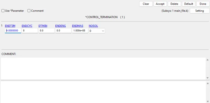
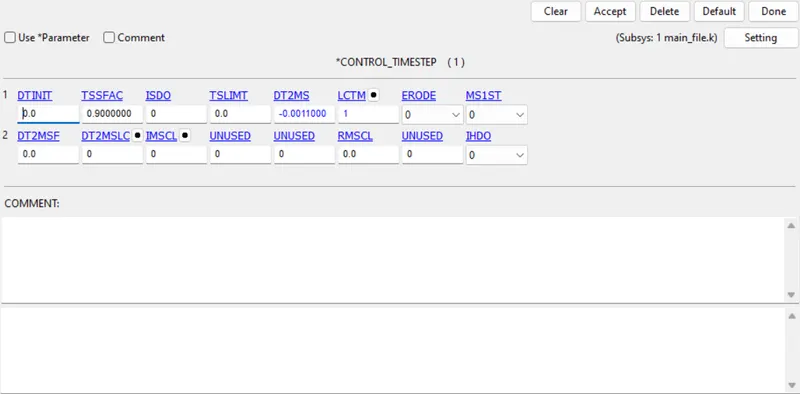
- The next step is to define Control_Timestep and Control_Termination card.
- The next step is to define the database for the result extraction and plotting of different outcomes.
Case-2: (Headform provided with the Meshed Hood)
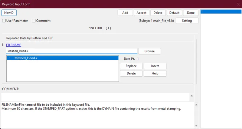
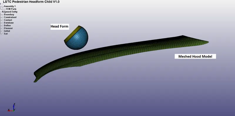
- The first step is to open a new window of LS-Dyna and use the include keyword to open the Meshed-Hood model in the file.
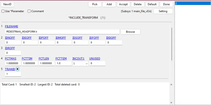
- The next step is to open the Simple_Head_Model in an inclined way. To make it happen Include_Transform keyword has been used.
- Then save the file in a new folder where both files are present.
- Now when we open the saved file in a new window we can see both the head form and hood model are brought into the same file.
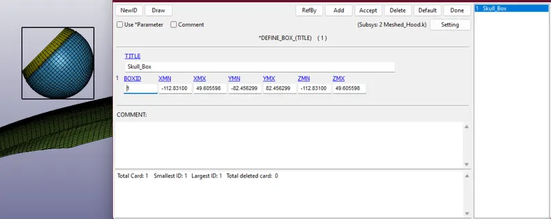
- The next step is to define a box for the head where we can use it to define the velocity card.
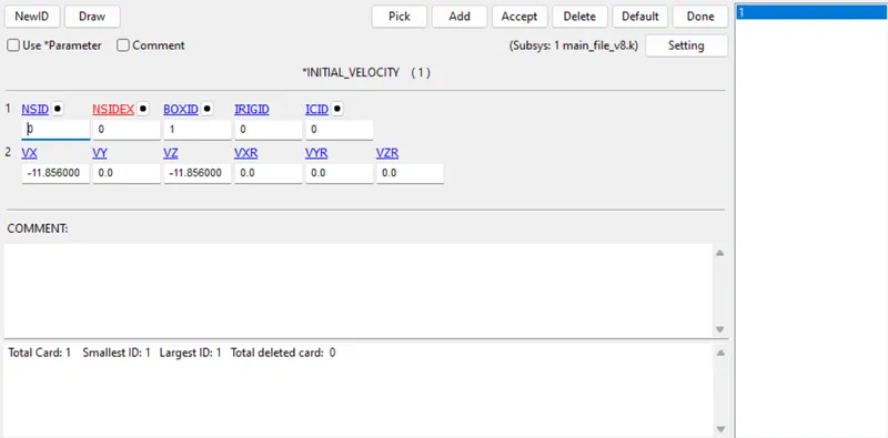
- The next step is to define velocity for the skull to emulate the real-world situation.
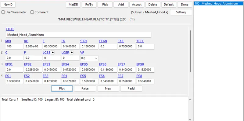
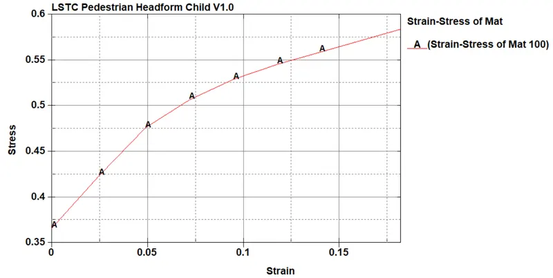
- The next step is to define the material cards for the skin and hood. For the hood, I've defined a piecewise-plastic card with Aluminium as material and for the skin of the head, I've defined an Ogden card with rubber as material.
- Material card for the hood-
- Material card for the skin-
- Material card for the hood-
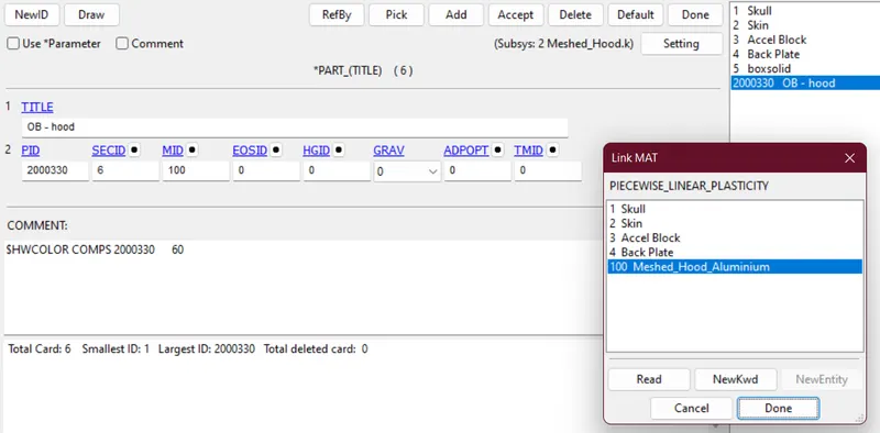
- The next step is to apply the material cards to the respective part in order to maintain continuity.
- Skin
- Hood
- Skin
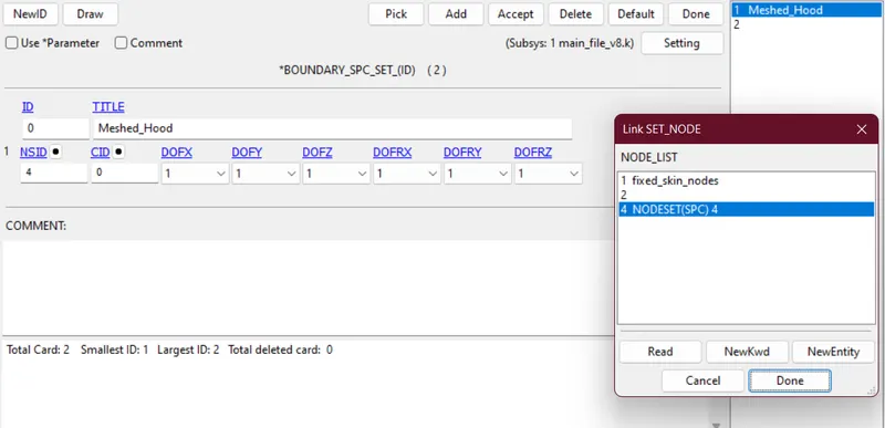
- The next step is to define the boundaries for the hood to make the model stable.
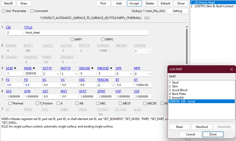
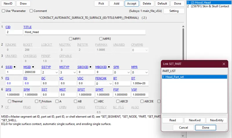
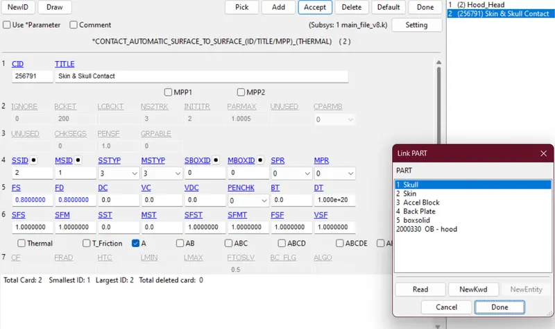
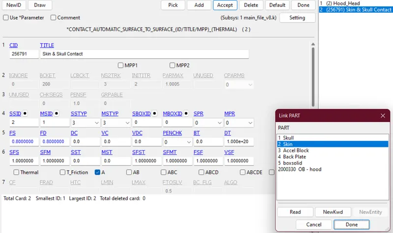
- The next step is to define contact in our model such that we can capture the whole deformation. Mainly they are two contacts Head & hood, and Skull & Skin.
- Head & hood:- I've modelled the contact as Automatic_Surface_to_Surface type where the master segment is hood and the slave segment is head part set.
- Master Segment
- Slave Segment
- Master Segment
- Skull & Skin:- There's another contact between the skull and skin of the head which can be modelled by the Automatic_Surface_to_Surface card where the master segment is skull and slave segment is the skin.
- Master Segment:
- Slave Segment:
- Master Segment:
- Head & hood:- I've modelled the contact as Automatic_Surface_to_Surface type where the master segment is hood and the slave segment is head part set.
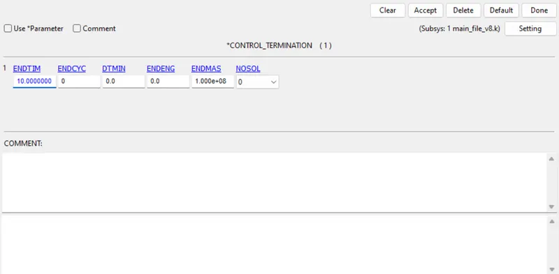
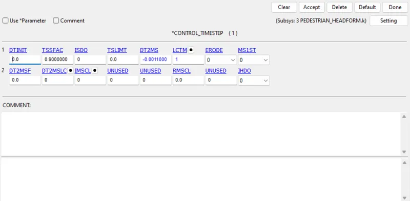
- The next step is to create control cards such as Control_Timestep and Control_Termination.
- Control_Timestep
- Control_Termination
- Control_Timestep
- The next step is to create a database where I've created ASCII_OPTIONS, BINARY_D3PLOT, and HISTORY_NODE_ID data sets.
Results & Plots
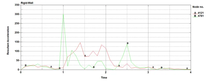
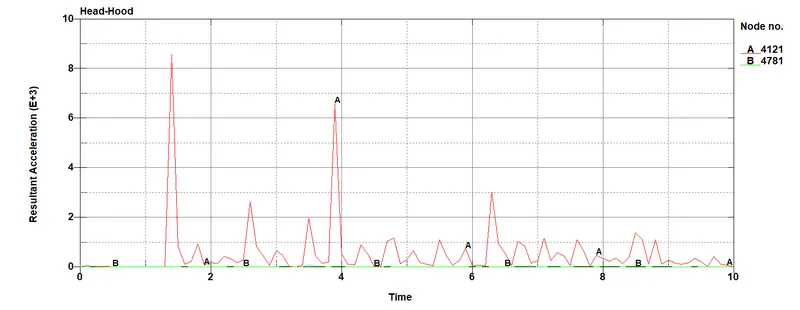
- The first comparison of the results is the acceleration of headform due to impact.
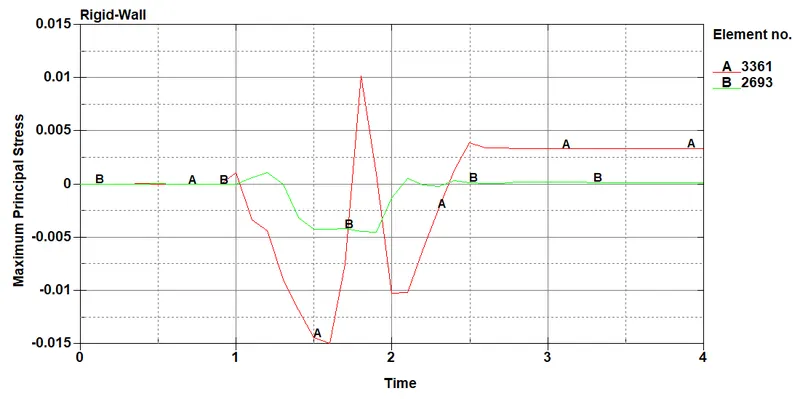
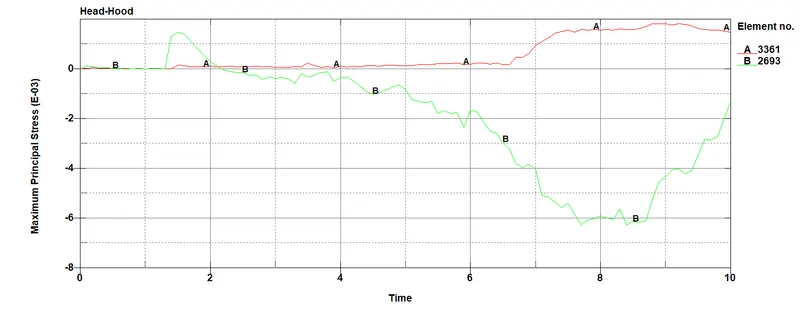
- The next comparison of the results is the maximum principal stress generated in the skin of the headform.
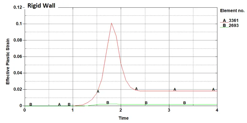
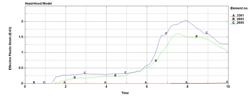
- The next comparison is between effective plastic strain in the head for both cases.
Conclusion
- From the above assignment, I've learned the post-processing of a case where we have to deal with similar problems with a slight difference in the situation.
- I've also learned about the modelling of situations which are very close to reality.
- I've also got exposure to the modelling of different materials like Ogden, Piecewise plastic etc.
- It is also very important to emulate the contacts to get proper results which can be translated into reality.