Week-7 Head Impact
Head Impact Analysis
Aim
The aim of the analysis is to conduct a pedestrian head impact simulation on the vehicle bonnet.
Case Setup
The setup of the analysis is divided into three cases:
1. The impact simulation of a simple head impact with a rigid wall.
2. The impact simulation of the headform provided with the rigid wall.
3. The impact simulation of the head form with the hood (vehicle bonnet).
The setup of each case will be discussed separately and the results will be compiled in later sections.
Case 1
Simple head impact with rigid wall
1. Units
The units utilized for the task are:
Kg-mm-ms
2. 3D Model
The 3D model of the simple head is provided in a separate file. The simple head model is a spherical shaped head model as shown in the figure below:
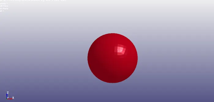
Figure 1 Simple head 3D model (Spherical).
The rigid wall is modeled using Rigidwall_Planar command in Create Entity section of Model & Part.
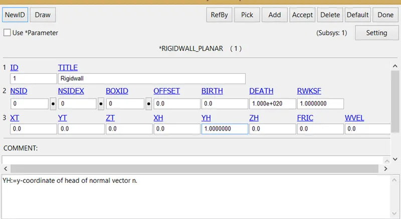
Figure 2 Rigidwall_Planar card for defining plane rigidwall. Note: Here XT, YT, ZT & XH, YH & ZH are tail and head co-ordinates of the normal vector to the plane.
Overall Positioning of the head and rigidwall is illustrated in the following figure.
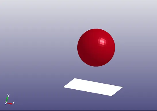
Figure 3 Simple head positioned above planar rigidwall before impact.
3. Material Property
Simple Head
The material card used for representing simple head is MAT_ELASTIC with the following arbitrary properties:
Density: 5e-6 kg/mm3
Elastic Modulus: 210 GPa
Poisson Ratio: 0.3
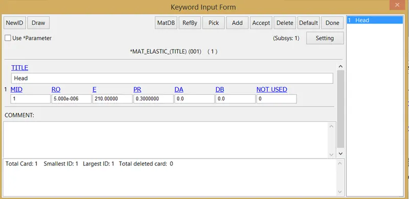
Figure 4 Material property card for the simple head.
Rigidwall
The material for the rigidwall is automatically defined as rigid material through the rigidwall definition card.
4. Boundary Conditions
Rigidwall (Planar)
A plane rigidwall is defined using RIGIDWALL PLANAR to simulate the vehicle hood as the rigidwall, as shown in figure below:
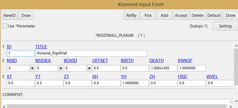
Figure 5 Rigidwall Planar keyword to define the plane rigidwall.
5. Define
The following type of define is utilized:
Define Transformation
This card is used for referencing the transformation of a subsystem file included via INCLUDE_TRANSFORM.
Translational transformation is used as shown in the figure below.
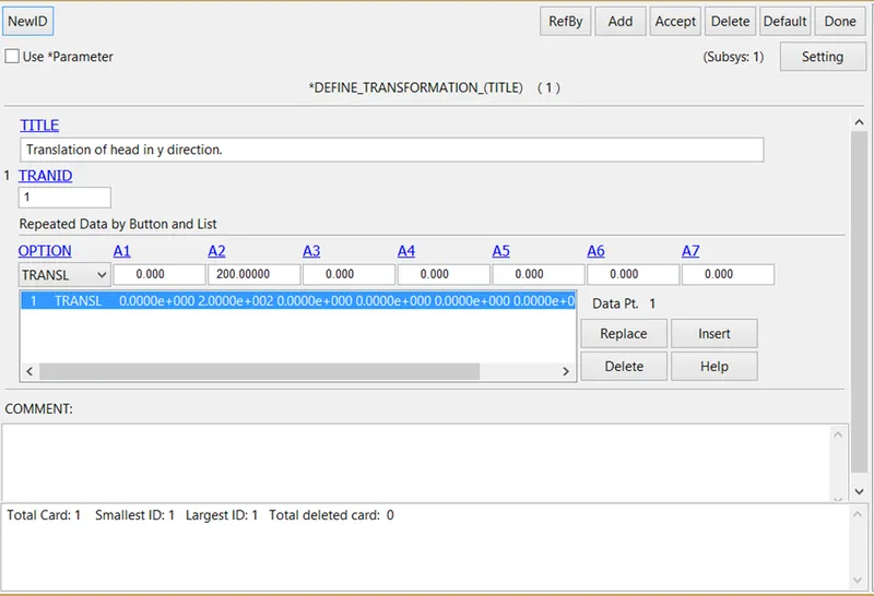
Figure 6 Translational transformation card for referencing transformation in the included file.
Here A1, A2 & A3 define the translation of the subjected subsystem in x, y & z coordinates respectively.
6. Include
Include_Transform is used for including the Simple Head file into the main file.
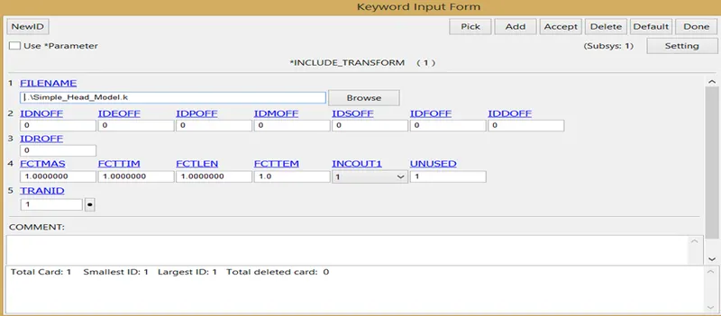
Figure 7 Include keyword with TRANID =1 is used to reference the transformation provided in the defined keyword.
7. Initial
Initial Velocity
The initial keyword is used to provide the initial boundary condition (before the impact boundary condition). The initial boundary condition is provided in the form of the velocity of the impact of the simple head with the rigid wall. Initial Velocity is used for defining the velocity of impact.
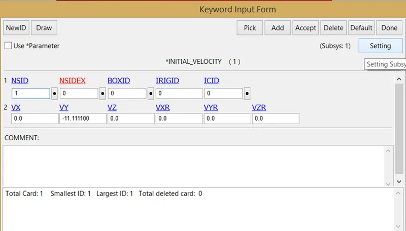
Figure 8 Initial Velocity card for defining velocity of impact during a crash.
• In the card, NSID = 1 represents the entities on which the boundary condition is applied (NSID =1, represents all the nodes of the head).
• Vy =-11.111 represents the negative y-direction velocity of 11.1 m/sec (i.e. 40 kmph)
8. Section
Section Shell
This card is used to define the sectional properties of the shell elements of the head for numerical computation of the elements during a crash.
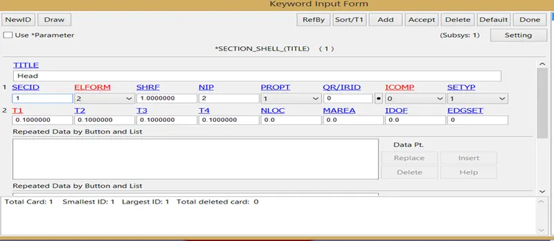
Figure 9 Defining sectional properties of the shell elements of the head.
9. Contact
Although the contact between rigidwall and the simple headform is automatically defined through the definition of rigidwall, the self-contact of the simple headform is to be additionally defined.
Contact Automatic Single Surface
This card is used for defining the self-contact of the simple headform during a crash.
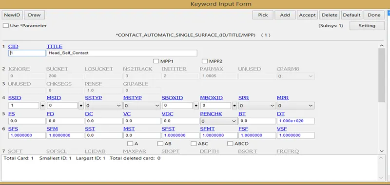
Figure 10 Contact card for defining self-contact of the simple headform.
All the segments of the simple headform are included in the SSID (Slave Set ID).
10. Control
Control Termination
This card was used to define the simulation time of 100 msec.
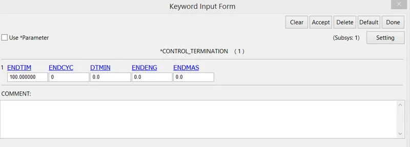
Figure 11 Termination time of the crash simulation is defined using control termination.
11. Database
Binary D3plot
This card is used for post-processing purposes and for a visual representation of the crash simulation. The time interval between outputs of d3plot files is 0.1 msec.
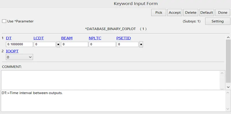
Figure 12 Database Binary D3plot card for post-processing of the simulation.
12. Part
This keyword is used to integrate sectional and material properties into the part.
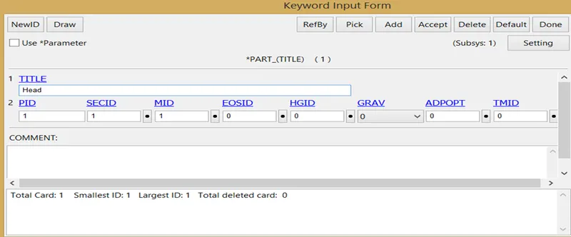
Figure 13 Part keyword to define the sectional and material properties to the simple headform.
Case 2
Impact simulation of the headform with the rigidwall
1. Units
The units utilized for the task are:
Kg-mm-ms
2. 3D Model
The 3D model of the headform assembly is provided in a separate file. The headform model is shown in the figure below:
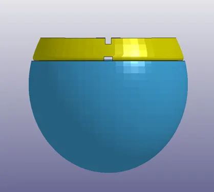
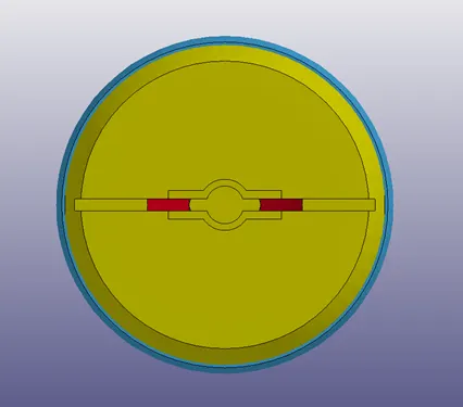
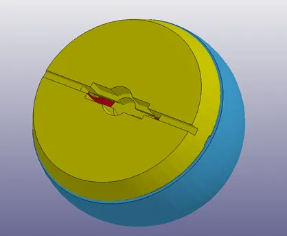
Figure 14 Headform assembly views
The components/parts of the assembled headform are as follows:
• Skull – Represents the skull bone of the headform.
• Skin – Represents the outer skin covering of the skull.
• Acceleration block – This is used for defining the nodal acceleration point of reference in the skull.
• Backplate.
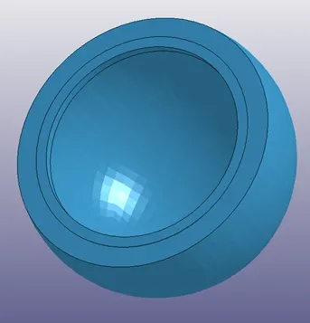
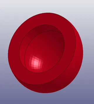
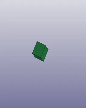
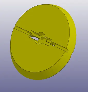
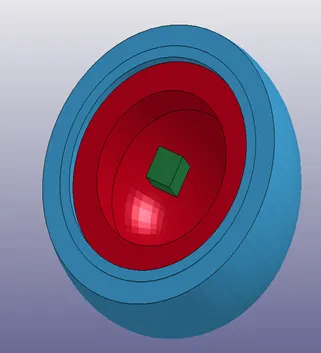
Figure 15 3D model of (1) Skin (2)Skull (3) Acceleration block (4) Back Plate (5) Assembly of Skin, Skull & Acceleration block (Left to Right & Up to down)
3. Material
Different material cards with suitable properties are used to define the material properties of respective parts, stated as follows:
Skull – MAT RIGID
MID =1
Density = 2.90e-6 kg/mm3
Elastic Modulus (E) = 207 GPa
Poisson Ratio = 0.28
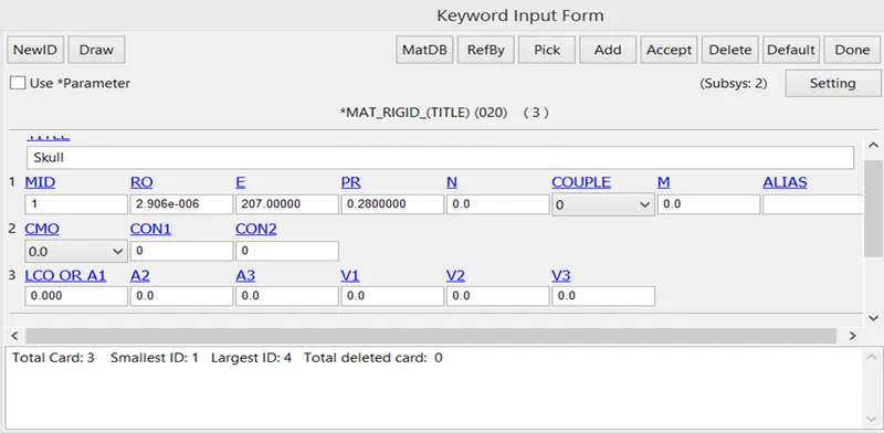
Figure 16 Material Definition card for skull part of the headform.
Skin – MAT OGDEN RUBBER
MID = 2
Density = 1.088e-6 kg/mm3
Poisson Ratio = 0.493
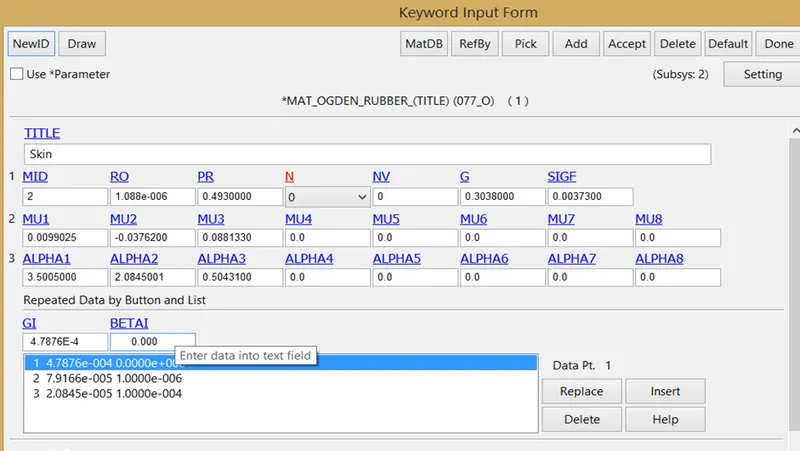
Figure 17 Material Definition card for skin part of the headform.
Acceleration Block – MAT RIGID
MID = 3
Density = 3.150e-6 kg/mm3
Elastic Modulus (E) = 207 GPa
Poisson Ratio = 0.28
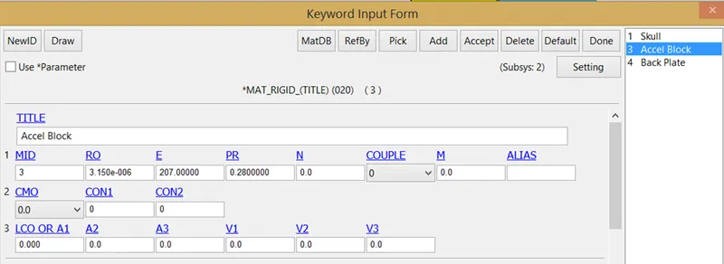
Figure 18 Material Definition card for acceleration block part of the headform.
Back Plate – MAT RIGID
MID = 4
Density = 3.150e-6 kg/mm3
Elastic Modulus (E) = 207 GPa
Poisson Ratio = 0.28
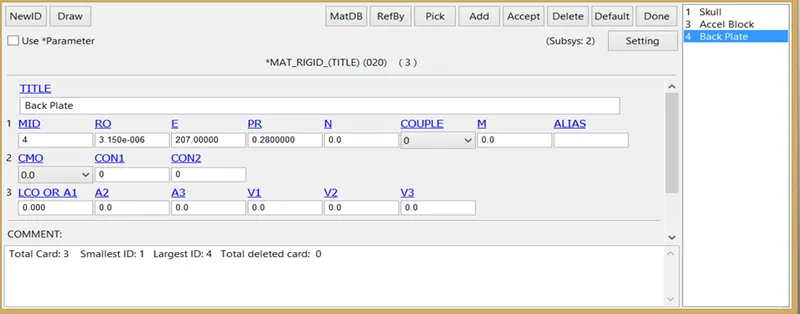
Figure 19 Material Definition card for back plate part of the headform.
4. Control
Control Termination
This keyword is used to define the simulation termination time. For this simulation the termination time is 50 msec.
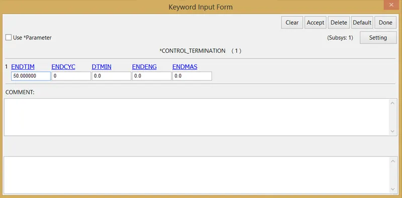
Figure 20 Defining simulation time using Control Termination.
5. Define
Define Transformation
This keyword is used to position the headform according to the specifications provided.
• Step 1
In this step, the headform is rotated about X-axis by 90 degrees.
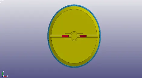
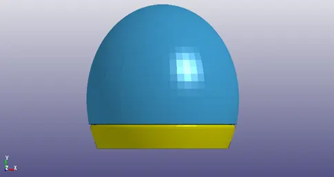
Figure 21 Initial orientation of Headform (Left) & Orientation of headform after first transformation (90 degrees rotation about X-axis) (Right)
• Step 2
In this step, the headform is translated by 200 units (mm) in negative y direction.
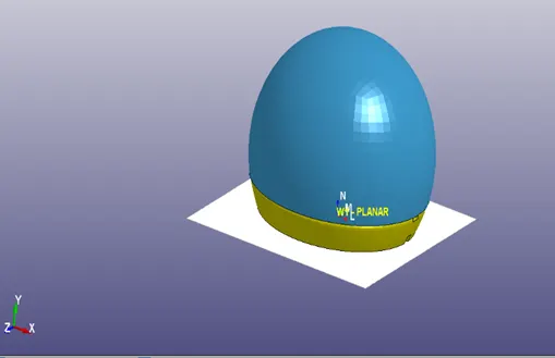
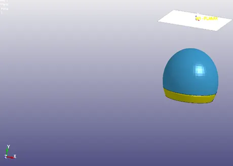
Figure 22 Initial orientation of Headform w.r.t. rigidwall before second transformation (Left) & Orientation of headform w.r.t. rigidwall after second transformation (Translated by 200 mm in –ve y direction) (Right)
• Step 3
In this step, the headform is rotated about Z-axis by 130 degrees so as to fulfill the requirement of 40 degrees inclination w.r.t. rigidwall during impact.
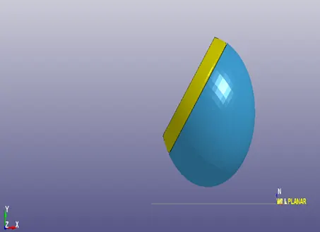
Figure 23 Initial orientation of Headform w.r.t. rigidwall before third transformation (Left) & Orientation of headform w.r.t. rigidwall after third transformation (Rotated by 130 degrees about z-axis) (Right)
6. Include
Include Transform
This keyword is used to include the transformed headform subsystem into the main file. The transformation to be applied on the headform via Define Transformation keyword is referenced here.
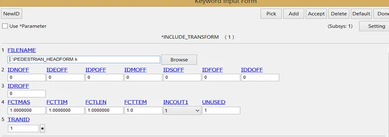
Figure 24 Include transformation keyword, for including the headform file with desired transformation.
7. Initial
Initial Velocity
This keyword is used to provide velocity to the headform as an initial boundary condition. The head impact is simulated at a velocity of magnitude 40 kmph (11.1 mm/msec) in negative y direction (as shown in figure below).
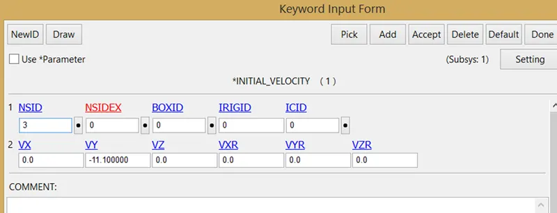
Figure 25 Initial Velocity keyword used for applying initial impact velocity to the headform w.r.t. the car hood (rigidwall).
8. Boundary Conditions
Rigidwall (Planar)
A plane rigidwall is defined using RIGIDWALL PLANAR to simulate the vehicle hood as the rigidwall, as shown in figure below:
Figure 26 Rigidwall Planar keyword to define the plane rigidwall.
9. Section
Section Solid
The section properties of the solid elements of the parts of Headform are defined in the keyword. The ELFORM = 1 (Constant stress solid element formulation) is used for all the elements, as shown in figure below:
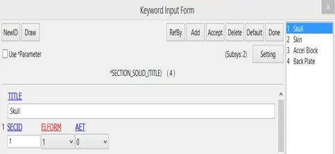
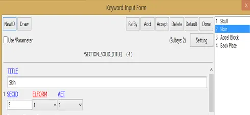
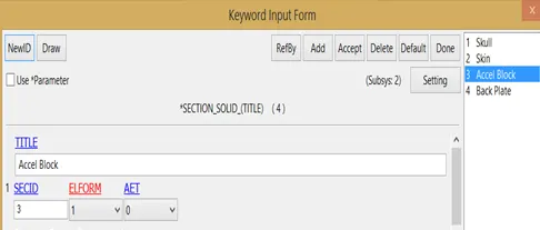
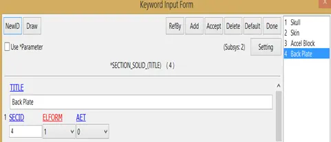
Figure 27 Sectional properties of solid elements of each part are defined using Section Solid
10. Part
This keyword is used to integrate sectional and material properties into the part.
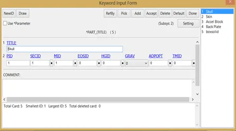
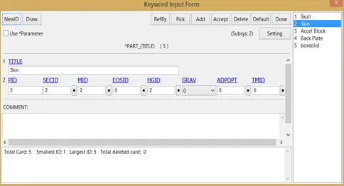
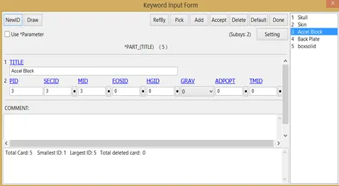
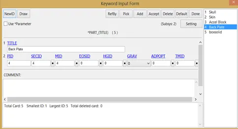
Figure 28 Part Keyword for integrating material & sectional properties to all the respective parts.
11. Database
Binary D3plot
This card is used for post-processing purposes and for a visual representation of the crash simulation. The time interval between outputs of d3plot files is 0.1 msec.
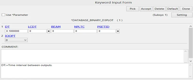
Figure 29 Database Binary D3plot card for post-processing of the simulation.
History Node ID
This keyword is used for selecting a suitable node for evaluating HIC values of the head during impact. The considerations behind selecting a specific node id for calculating HIC values are based on practical experimentation (however, the selected node should be around center of the head, so as to represent the acceleration of the inner sensitive parts of the brain due to impact).
Node ID 25679 is selected in this case.
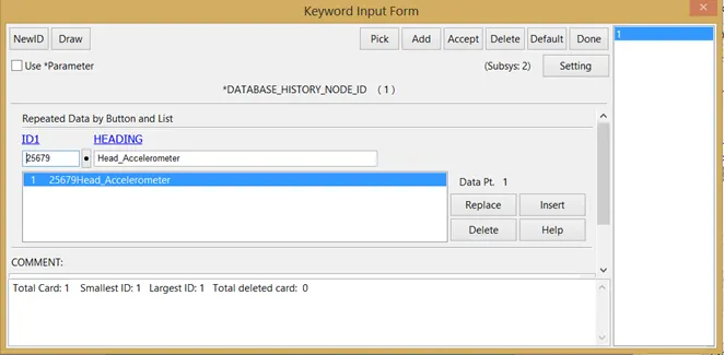
Figure 30 Node Id selection for HIC calculation.
ASCII Option (NODOUT)
NODOUT is referenced for the node id selected for calculating acceleration and HIC values. The selected node id is at the center of the acceleration block and is chosen by the headform design team. The time between outputs (DT) is 0.1 msec.
Extent Binary
This card is used to dump strain tensor values in the d3plot files. The STRFLG is set to 1 for including strain data in the simulation, as shown in the figure below.
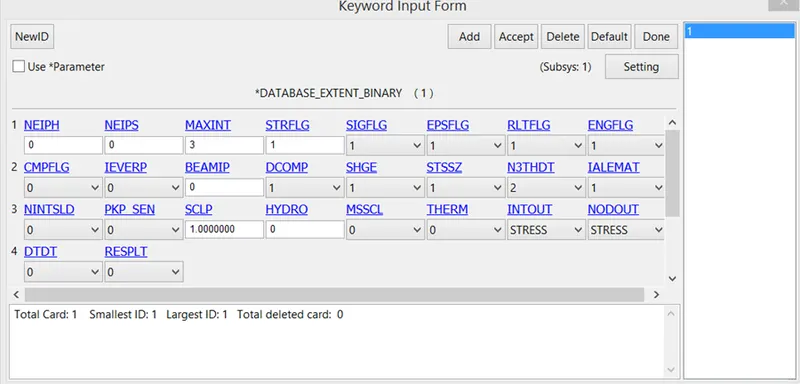
Figure 31 Extent binary keyword, to include strain data in binary d3plot file, by switching STRFLG to 1.
Case 3
The impact simulation of the head form with the hood (vehicle bonnet).
1. Units
The units utilized for the task are:
Kg-mm-ms
2. 3D Model
Headform Assembly
The 3D model of the headform assembly is provided in a separate file. The headform model is shown in figure below:
Figure 32 Headform assembly views
The components/parts of the assembled headform are as follows:
• Skull – Represents the skull bone of the headform.
• Skin – Represents the outer skin covering of the skull.
• Acceleration block – This is used for defining the nodal acceleration point of reference in the skull.
• Backplate.
Figure 33 3D model of (1) Skin (2)Skull (3) Acceleration block (4) Back Plate (5) Assembly of Skin, Skull & Acceleration block (Left to Right & Up to down)
Hood (Vehicle Bonnet)
The 3D model of the hood (Vehicle Bonnet) is provided in a separate file, as shown in the figure:
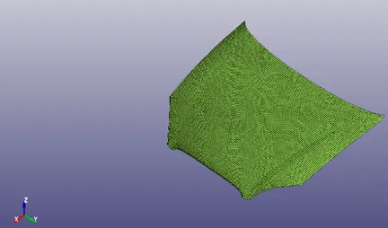
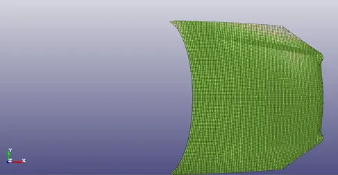
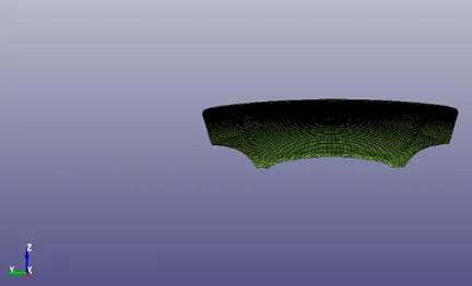
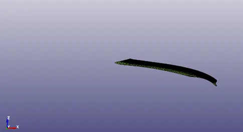
Figure 34 Isometric, Top, Front and Side Views of the 3D model of Vehicle Bonnet (Hood)
Headform & Hood Assembly
The following figure shows the orientation of the headform with respect to the hood.
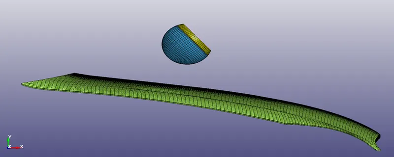
Figure 35 Headform orientation with respect to the hood.
3. Material
Different material cards with suitable properties are used to define the material properties of respective parts, stated as follows:
Skull – MAT RIGID
MID =1
Density = 2.90e-6 kg/mm3
Elastic Modulus (E) = 207 GPa
Poisson Ratio = 0.28
Figure 36 Material Definition card for skull part of the headform.
Skin – MAT OGDEN RUBBER
MID = 2
Density = 1.088e-6 kg/mm3
Poisson Ratio = 0.493
Figure 37 Material Definition card for skin part of the headform.
Acceleration Block – MAT RIGID
MID = 3
Density = 3.150e-6 kg/mm3
Elastic Modulus (E) = 207 GPa
Poisson Ratio = 0.28
Figure 38 Material Definition card for acceleration block part of the headform.
Back Plate – MAT RIGID
MID = 4
Density = 3.150e-6 kg/mm3
Elastic Modulus (E) = 207 GPa
Poisson Ratio = 0.28
Figure 39 Material Definition card for backplate part of the headform.
Hood (Vehicle Bonnet) – MAT Power Law Plasticity (Aluminium)
MID – 6
Density (RO) – 2.698e-6
Elastic Modulus (E) – 68.9 GPa
Poisson Ratio (PR) – 0.33
Strength Coefficient (K) – 0.777 GPa
Hardening Coefficient (N) – 0.45
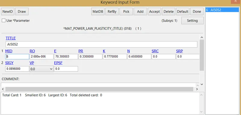
Figure 40 MAT Power Law Plasticity model is used to simulate the plastic behavior of Aluminium Hood.
4. Control
Control Termination
This keyword is used to define the simulation termination time. For this simulation the termination time is 50 msec.
Figure 41 Defining simulation time using Control Termination.
5. Define
Define Transformation
This keyword is used to position the headform according to the specifications provided.
• Step 1
In this step, the headform is rotated about X-axis by 90 degrees.
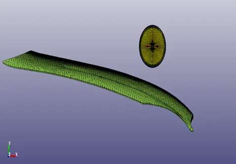
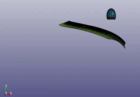
Figure 42 Initial orientation of Headform (Left) & Orientation of headform after the first transformation (90 degrees rotation about X-axis) (Right)
• Step 2
In this step, the headform is translated by 200 units (mm) in the negative y-direction.
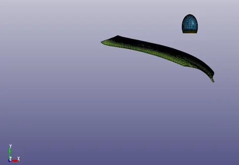
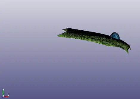
Figure 43 Initial orientation of Headform w.r.t. hood before the second transformation (Left) & Orientation of headform w.r.t. hood after the second transformation (Translated by 200 mm in –ve y-direction) (Right)
• Step 3
In this step, the headform is rotated about Z-axis by 130 degrees so as to fulfill the requirement of 40 degrees inclination w.r.t. hood during impact.
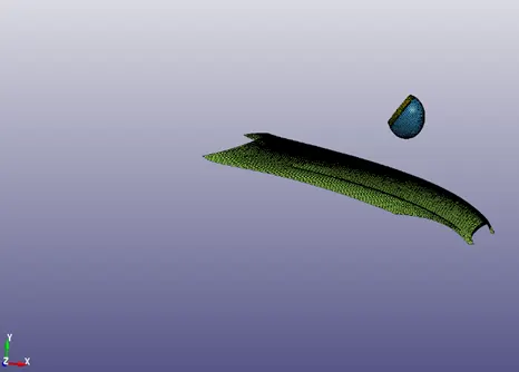
Figure 44 Initial orientation of Headform w.r.t. hood before the third transformation (Left) & Orientation of headform w.r.t. hood after the third transformation (Rotated by 130 degrees about the z-axis) (Right)
• Step 4
In this step, the headform is translated by 200 units (mm) in negative x direction.
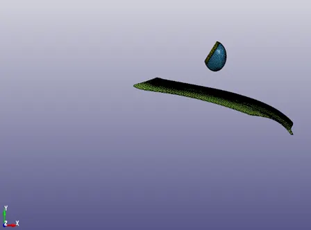
Figure 45 Initial orientation of Headform w.r.t. hood before the second transformation (Left) & Orientation of headform w.r.t. hood after the second transformation (Translated by 200 mm in –ve x-direction) (Right)
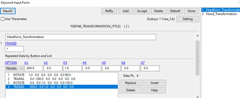
Figure 45 Headform Transformation Keyword used to define all the headform transformations (Step 1 to Step 4)
6. Include
Include Transform
This keyword is used to include the transformed headform subsystem into the main file. The transformation to be applied on the headform and hood via Define Transformation keyword is referenced here.
Figure 46 Include transformation keyword, for including the headform file with the desired transformation.
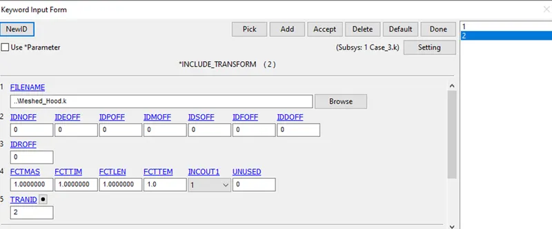
Figure 47 Include transformation keyword, for including the hood file with the desired transformation.
7. Initial
Initial Velocity
This keyword is used to provide velocity to the headform as an initial boundary condition. The head impact is simulated at a velocity of magnitude 40 kmph (11.1 mm/msec) in the negative y-direction (as shown in the figure below).
Figure 48 Initial Velocity keyword used for applying initial impact velocity to the headform w.r.t. the car hood (rigidwall).
8. Section
Section Solid
The section properties of the solid elements of the parts of Headform are defined in the keyword. The ELFORM = 1 (Constant stress solid element formulation) is used for all the elements, as shown in the figure below:

Figure 49 Sectional properties of solid elements of each part are defined using Section Solid & Section Shell (for hood)
9. Part
This keyword is used to integrate sectional and material properties into the part.
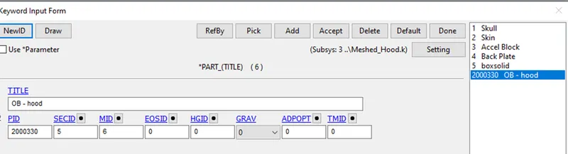
Figure 50 Part Keyword for integrating material & sectional properties to all the respective parts.
10. Contact
Contact Automatic Surface to Surface
The contact between headform and hood is defined using this keyword, as shown in figure below:
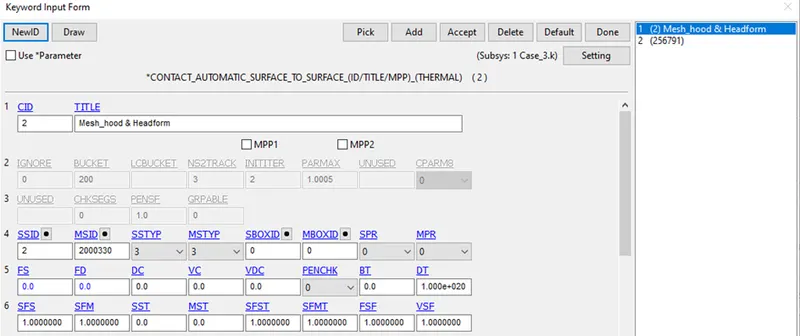
Figure 51 Contact Automatic Surface to Surface for contact definition between hood and headform.
11. Database
Binary D3plot
This card is used for post-processing purposes and for a visual representation of the crash simulation. The time interval between outputs of d3plot files is 0.1 msec.
Figure 52 Database Binary D3plot card for post-processing of the simulation.
History Node ID
This keyword is used for selecting a suitable node for evaluating HIC values of the head during impact. The considerations behind selecting a specific node id for calculating HIC values is based on practical experimentation (however, the selected node should be around the center of the head, so as to represent the acceleration of the inner sensitive parts of the brain due to impact).
Node ID 25679 is selected in this case.
Figure 53 Node Id selection for HIC calculation.
ASCII Option (NODOUT)
NODOUT is referenced for the node id selected for calculating acceleration and HIC values. The selected node id is at the center of the acceleration block and is chosen by the headform design team. The time between outputs (DT) is 0.1 msec.
Extent Binary
This card is used to dump strain tensor values in the d3plot files. The STRFLG is set to 1 for including strain data in the simulation, as shown in the figure below.
Figure 54 Extent binary keyword, to include strain data in binary d3plot file, by switching STRFLG to 1.
Conclusion
Case 1 represents the most simplistic version of the actual crash, and thus the results obtained from case 1 are also realistically less significant, however, gradually increasing the complexity from case 1 to case 3 helps us to better understand the system.
Case 1
The results of case 1 include only a screenshot of impact during simulation, as shown in the figure below:
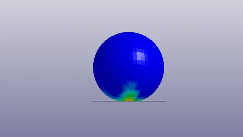
Figure 55 A still from the case 1 simulation, depicting the impact of simple headform with the rigidwall, and the corresponding stresses obtained in the headform.
Case 2
Acceleration plot and HIC calculation
The time vs acceleration plots is formed for the selected element (ID – 25679). The reason for the selection of the element is based on the experiments that have recommended the suitability of the selection of a central element. The reason for the recommendation can be based on the standards specified for the calculation of HIC, however, the exact details of selection are to be consulted by the headform designing team.
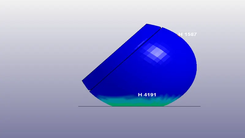
Figure 56 A still from the case 2 simulation, depicting the impact of headform with the rigidwall, and the corresponding stresses obtained in the headform.
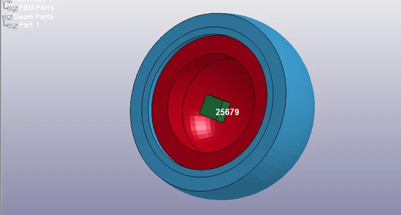
Figure 57 Figure depicting, location of the selected node ID (ID -25679 (inside the acceleration box, green color).
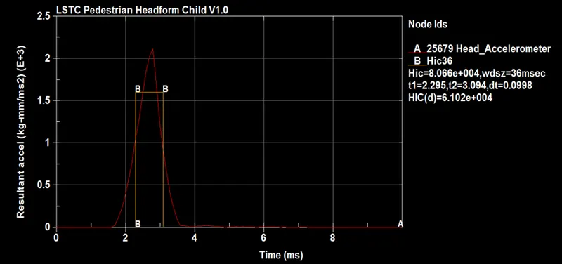
Figure 58 Acceleration plot of node ID 25679, with calculated HIC 36 value = 80660 (approx.), & HIC (d) = 6.102e+004
Stress-Strain plot
The selected element for the stress-strain plot is H3290. The element is selected because of the following reasons:
• H3290 is the element of the simulated skin part (this part is the only non-rigid part in the system), and the elements of the rigid parts would not show any stress and strain due to their rigidity.
• Element H3290 is along the line of impact. This line of impact is normal to the plane of impact between headform and rigidwall, and hence any element along the line of impact will bear most of a load of impact contributing to maximum stresses and strains involved.
The figure below shows the stresses along the X, Y & Z direction in element H3290. The reason for the maximum magnitude of y-direction stress is due to the fact that the line of impact is parallel to the y axis. The reason for zeroing of the stresses after 4 ms is because the headform has bounced off the rigidwall, and thus the stresses have relaxed after the initial compression of the headform.
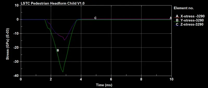
Figure 59 Directional stresses in H 3290 due to the impact.
Considering Y directional stress as the dominant stress, we would be restricting stress strain plots for Y directional stress.
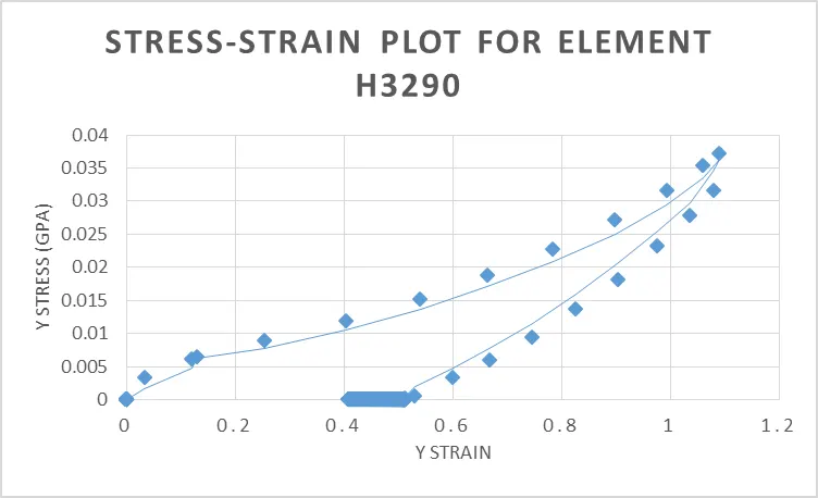
Figure 60 Stress-Strain plot for element H3290
Case 3
Acceleration plot and HIC calculation
The time vs acceleration plots is formed for the selected element (ID – 25679). The reason for the selection of the element is based on the experiments that have recommended the suitability of the selection of a central element. The reason for the recommendation can be based on the standards specified for the calculation of HIC, however, the exact details of selection are to be consulted by the headform designing team.
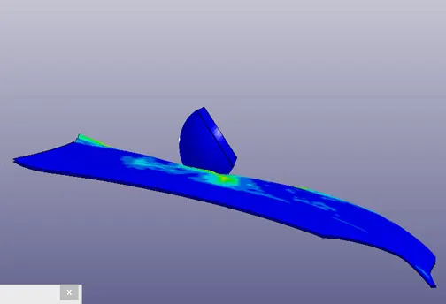
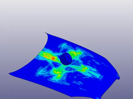
Figure 61 A still from the case 2 simulation, depicting the impact of headform with the rigidwall, and the corresponding stresses obtained in the headform.
The acceleration plot for case 3 is quite insignificant in comparison with that for case 2, also the HIC values are minimal, suggesting that the chances of head injury in case 3 are very less in comparison with that of case 2.
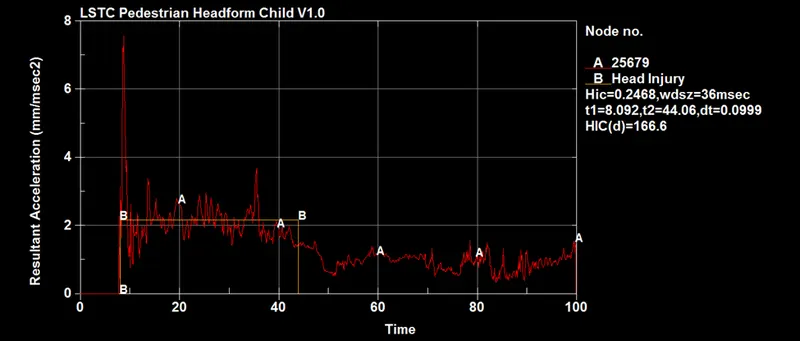
Figure 62 Acceleration plot of node ID 25679, with calculated HIC 36 value = 0.2468 (approx.), & HIC (d) = 166.6
Stress-Strain plot
The stress-strain plot is also quite insignificant in case 3 as the strain values of H3290 are very less. The image below shows the stress-strain relation for the case, however proper stress-strain correlation could not be tracked due to minimal values of strain in the case.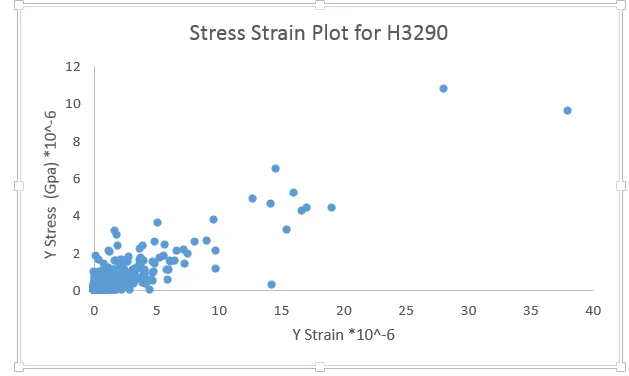
Figure 63 Stress-Strain plot for element H3290
Result comparison between case 2 & case 3
The following table shows the contrast between results obtained for case 2 and case 3.
|
Case 2 |
Case 3 |
|
|
HIC 36 (d) |
61020 |
166.6 |
|
Stress-Strain |
Significant stresses and strain |
Insignificant stress and strain |
|
Max. Acceleration (mm/msec2) |
2100 (approx.) |
10 (approx.) |
EXPLANATION
The reason for the reduced acceleration, HIC, and stress-strain in case 3 is due to the shock-absorbing and deformation capability of the aluminum hood. The aluminum hood plastically deforms during impact simulation so as to reduce the resisting impulse on the headform due to impact.