Week - 5 - Modelling Spotwelds
Spot-weld Modeling
Aim
To simulate spot-weld using beam and solid elements.
Explanation/ Case Setup
Case -1 (Beam Spot-welds)
Geometric shape and mesh of the shells to be spot-welded has been initially provided.
Diagram
In the case setup, 6 beam spotwelds are symmetrically placed, the beam spotwelds are symbolized by green marks in the diagram.

Figure 1 Top view of shells with beam spotweld

Figure 2 Front view of shells with beam spotweld

Figure 3 Side view of shells with beam spotweld
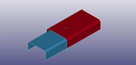
Figure 4 Isometric view of shells with beam spotweld
Units
The units used in the simulation is gm/mm/ms.
Material
Material for shell and beam elements is modeled using MAT keyword.
Shell Material
For shell parts, MAT-Plastic-Kinematic card is used to denote steel as material with following parameters (in g/mm/ms) with Material ID 2
Density - 0.007850
Young’s Modulus – 2.1e5
Poisson’s Ratio – 0.3
Yield Stress – 2.5e5
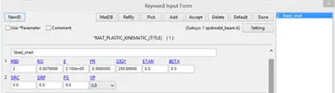
Figure 5 Material Properties of steel used in Shell using MAT-Plastic-Kinematic
Beam Material
For beam sections used in spotwelds, special material card MAT-Spotweld is used with following parametric values (in g/mm/ms) with Material ID 1.
Density – 0.007850
Young’s Modulus – 2.1e5
Yield Stress – 2.5e2
Plastic Hardening Modulus – 2.1e4
TFAIL (Failure Time) – 0.6
All other parameters are by default taken as zero.
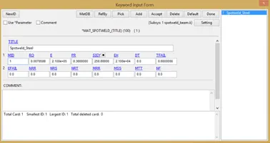
Figure 6 Material Properties of steel used in spotwelds, described using MAT-SPOTWELD
Beam Element Generation
Beam elements are generated using beam configuration with two node sets in Element Generation in Mesh toolbar.
Overall 6 beam elements are symmetrically defined about the loaded axis.
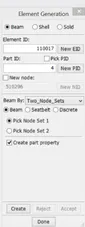
Figure 7 Element Generation Tab used to generate beam elements for beam spotwelds
Section
Section is to be defined for beam spotweld elements and shell parts.
Shell Section
The shell section is defined using shell card in section keyword with Section ID 2
The parameters defined for shell section formulation are exhibited in image below.
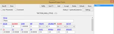
Figure 8 Parametric values for shell section
Beam Section
Beam section is defined using beam card in section keyword with Section ID 1. The parameters defined for beam section formulation are exhibited in image below.
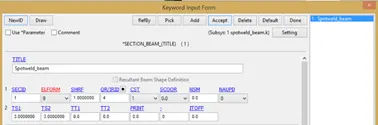
Figure 9 Parametric values for beam section
Part
Part keyword is defined to incorporate sectional and material properties into the part for simulation.
Three parts are defined in the simulation:
- Top part (Shell)
- Bottom part (Shell)
- Beam spotweld (Beam)
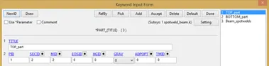
Figure 10 Part formulation for top part shell
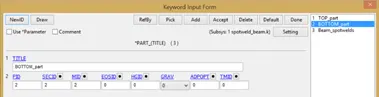
Figure 11 Part formulation for bottom part shell
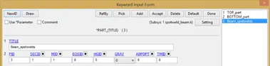
Figure 12 Part formulation for beam spotwelds
Boundary
Boundary condition is defined in two categories:
- Single point constraint (SPC), with specific node set.
- Prescribed motion set with specific node set.
SPC node set is defined for the nodes as illustrated in the following figure.
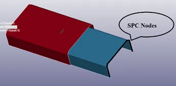
Figure 13 Picture illustrating the SPC (Single Point Constraint) nodes
Prescribed node set is defined for the nodes as illustrated in the following figure:
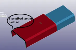
Figure 14 Picture illustrating prescribed motion node set subject to prescribed motion
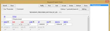
Figure 15 Prescribed motion card for defining prescribed motion to the node set
DOF =1, describes x translational degree of freedom
VAD =2, describes displacement as prescribed motion
LCID describes quantitatively displacement along time
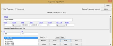
Figure 16 Diagram defining LCID parameters to quantitatively define displacement along time
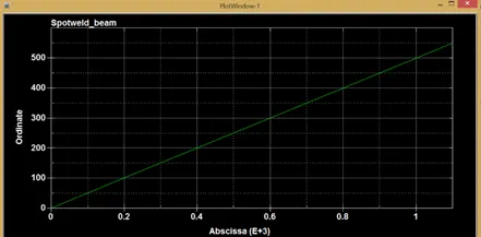
Figure 17 Displacement vs time plot
Control
This keyword is used to define the termination time of simulaton.

Figure 18 CONTROL_TERMINATION for defining termination time of simulation
Contact
Tied shell edge to surface
This card is used in under contact keyword, for defining tied contact between beam nodes and shell surface.
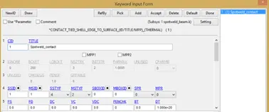
Figure 19 Defining contact between beam node-set and shell surface
SSID (Slave set ID) – 1 (Node set)
MSID (Master set ID) – 1 (Shell surface part set)
SSTYP (Slave set type) – 4 (Node set)
MSTYP (Master set type) – 2 (Part set)
Automatic Single Surface
This keyword is used to define self-contact between shell surfaces.
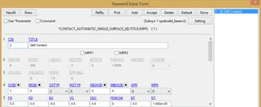
Figure 20 Defining self-contact between shell surfaces
SSID (Slave Set ID) – 1 (Shell surfaces)
SSTYP (Slave set Type) – 2 (Part Set)
MSID and MSTYP are ignored.
DATABASE
ASCII option
|
Serial NO. |
DATABASE OPTION |
DT (Time interval between outputs) (msec) |
|
1 |
GLSTAT |
1 |
|
2 |
MATSUM |
1 |
|
3 |
NODOUT |
1 |
|
4 |
SWFORC |
1 |
BINARY D3PLOT
Defines the binary plot files for illustrating the simulation.
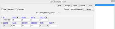
Figure 21 BINARY D3PLOT for defining binary d3plot files
HISTORY NODESET
Defines the node set to be included for writing NODOUT file.
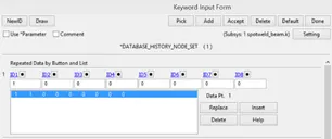
Figure 22 Node set ID to be included for NODOUT file in result.
Case -2 (SOLID Spot-welds)
Geometric shape and mesh of the shells to be spot-welded has been initially provided.
Diagram
In the case setup- 4 solid cuboidal spot welds are symmetrical placed about load axis.

Figure 23 Top view of setup with solid spot welds

Figure 24 Side view of setup with symmetrically placed spot welds between the shell surfaces
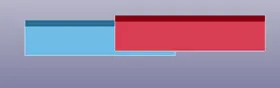
Figure 25 Front view of the setup
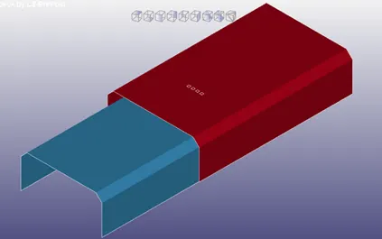
Figure 26 Isometric view of the setup
Units
The units used in the simulation is gm/mm/ms.
Material
Material for shell and beam elements is modeled using MAT keyword.
Shell Material
For shell parts, MAT-Plastic-Kinematic card is used to denote steel as material with following parameters (in g/mm/ms) with Material ID 2
Density - 0.007850
Young’s Modulus – 2.1e5
Poisson’s Ratio – 0.3
Yield Stress – 2.5e5
Figure 27 Material Properties of steel used in Shell using MAT-Plastic-Kinematic
Solid Spotweld Material
For beam sections used in spotwelds, special material card MAT-Spotweld is used with following parametric values (in g/mm/ms) with Material ID 1.
Density – 0.007850
Young’s Modulus – 2.1e5
Yield Stress – 2.5e2
Plastic Hardening Modulus – 2.1e4
TFAIL (Failure Time) – 0.6
All other parameters are by default taken as zero.
Figure 28 Material Properties of steel used in spot welds, described using MAT-SPOTWELD
Solid Element Generation
Cuboidal solid spot weld element is defined using shape-mesher in MESH keyword
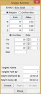
Figure 29 Defining solid spot-weld elements using shape-mesher
Section
Section is to be defined for solid spotweld elements and shell parts.
Shell Section
The shell section is defined using shell card in section keyword with Section ID 2
The parameters defined for shell section formulation are exhibited in image below.
Figure 30 Parametric values for shell section
Solid Spotweld elements
The solid section is defined using solid section card (as shown in figure below).
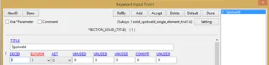
Figure 31 Defining solid section for solid spotwelds
Part
Part keyword is defined to incorporate sectional and material properties into the part for simulation.
Six parts are defined in the simulation:
- Top part (Shell)
- Bottom part (Shell)
- Solid spotweld (4 Cuboidal spotweld parts)
Figure 32 Part formulation for top part shell
Figure 33 Part formulation for bottom part shell
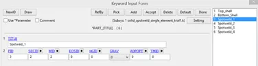
Figure 34 Part formulation for solid spotwelds
Boundary
Boundary condition is defined in two categories:
- Single point constraint (SPC), with specific node set.
- Prescribed motion set with specific node set.
SPC node set is defined for the nodes as illustrated in the following figure.
Figure 35 Picture illustrating the SPC (Single Point Constraint) nodes
Prescribed node set is defined for the nodes as illustrated in the following figure:
Figure 36 Picture illustrating prescribed motion node set subject to prescribed motion
Figure 37 Prescribed motion card for defining prescribed motion to the node set
DOF =1, describes x translational degree of freedom
VAD =2, describes displacement as prescribed motion
LCID describes quantitatively displacement along time
Figure 38 Diagram defining LCID parameters to quantitatively define displacement along time
Figure 39 Displacement vs time plot
Control
This keyword is used to define the termination time of simulation.
Figure 40 CONTROL_TERMINATION for defining termination time of simulation
DATABASE
ASCII option
|
Serial NO. |
DATABASE OPTION |
DT (Time interval between outputs) (msec) |
|
1 |
GLSTAT |
1 |
|
2 |
MATSUM |
1 |
|
3 |
SWFORC |
1 |
BINARY D3PLOT
Defines the binary plot files for illustrating the simulation.
Figure 41 BINARY D3PLOT for defining binary d3plot files
Contact
Contact between parts is established using two cards:
- Contact Spotweld (Contact between spotweld and shell surface)
- Automatic Single surface contact (Self contact)
Contact Spotweld
SSID – 2 (Spotwelds)
MSID – 1 (Shells)
SSTYP – 2 (Part Set)
MSTYP – 2(Part Set)
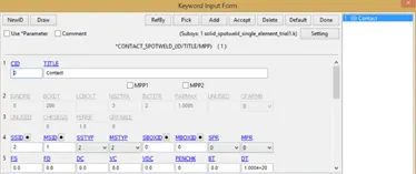
Figure 42 Spotweld Contact
Automatic Single Surface Contact
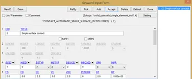
Figure 43 Self Contact
SSID – 1 (Shells)
SSTYP – 2 (Part Set)
Results
Axial force data for solid spotweld simulation
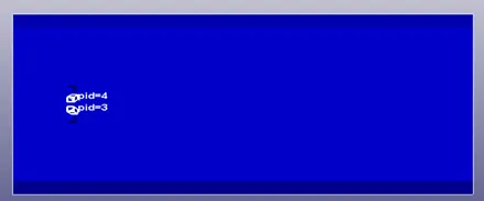
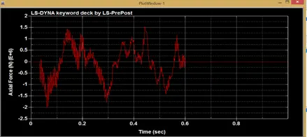
Figure 44 Axial force data for inner solid spotwelds
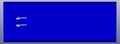
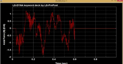
Figure 45 Axial force data for outer solid spotwelds
Shear force data for solid spotweld simulation
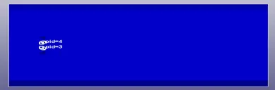
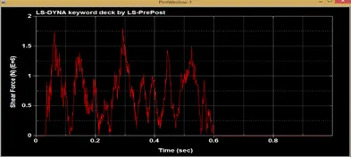
Figure 46 Shear force data for inner solid spotwelds
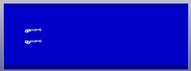
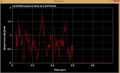
Figure 47 Shear force data for outer solid spotwelds
Swforc data for beam spotweld simulation
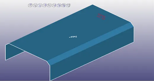
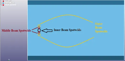
Figure 48 Illustration of terminologies for beam spotwelds
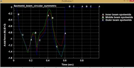
Figure 49 Axial force data for beam spotwelds
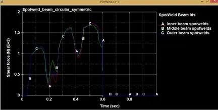
Figure 50 Shear force data for beam spotwelds
Conclusion
As seen from the plots, the axial forces and shear forces nullify after 0.6 sec, as the spotwelds fail @ 0.6 seconds.
Spot-weld Modeling