Week 7 - Creating connection for Rear door
Objective: Create and Apply different PIDs for different components and Perform suitable connections.
Given model: Rear automotive door, with more than 20+ components. As shown below,
Front View:
Rear View:
Procedure:
- Open the given ANSA file, And Assign PID for each component (Topo>faces> set PID)
- Examine the FE model to see the possible connection
- There are 4 types of connection required, those are
- Seam Weld
- Bolt
- Window damper (Window liner)
- Revit joint.
Seam Weld :
- Most of the Automotive parts parmantely joined with the help of seam welding method.
- Again there are two sub category of weld, Overlap and T- Weld.
- In overlap weld, both the plates are parallel to each other, where in T-weld, plates are perpendicular.
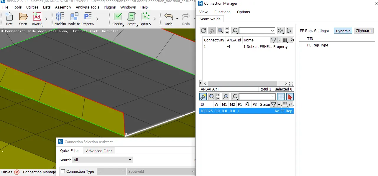
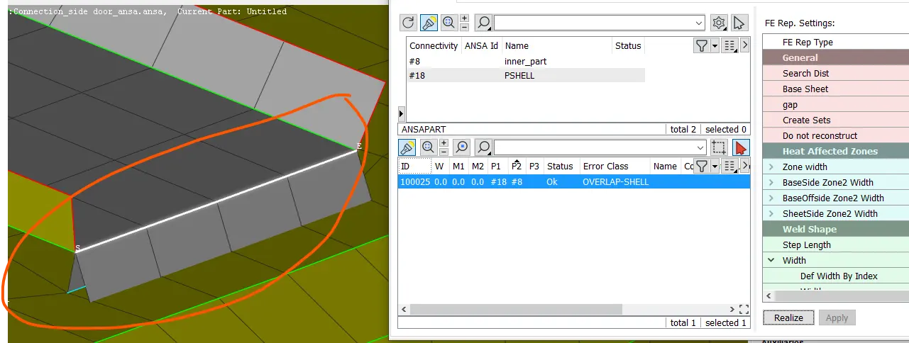
- Overlap seam weld:
- Create curved using FEA, ie (Mesh>perimeter>feat2Curve)
- Select the curve and convert it into seam line (Assembly tab>Convert>Curve>seam line)
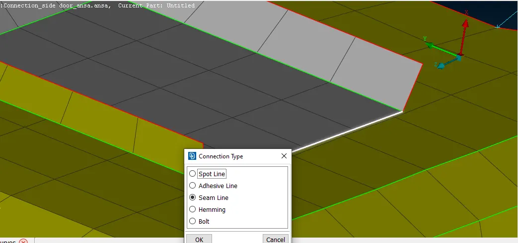
- Once the curve converted into seam line, the curve turn into bight pink curve.
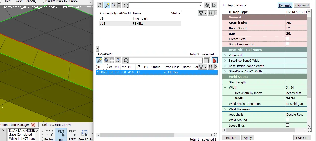
- Open connection Manager and select the seam line.
- Select P1 as base plate, second plate as P2.
- Select the FE rep Type as "Overlap-shell"
- Enter the Search distance, Element Step, weld width, Root shell (Primary, offset or Double) and set weld PID of the weld.
- Do, apply and realize.
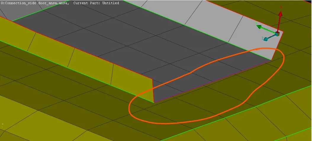
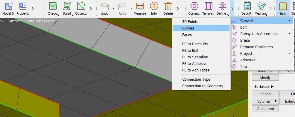
- Overlap seam weld:
- T-Seam Weld:
- Similar to overlap weld
- Select the FE rep Type as "Y-Joint shell"
- Enter the Search distance, Element Step, weld width, Root shell (Primary, offset or Double), Height(Optional) and set weld PID of the weld.
- Do, apply and realize.
- T-Seam Weld:
Bolt:
Bolt join can be don't either manually or automatically
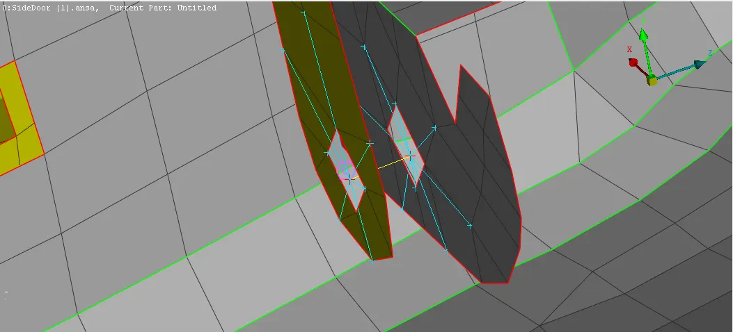
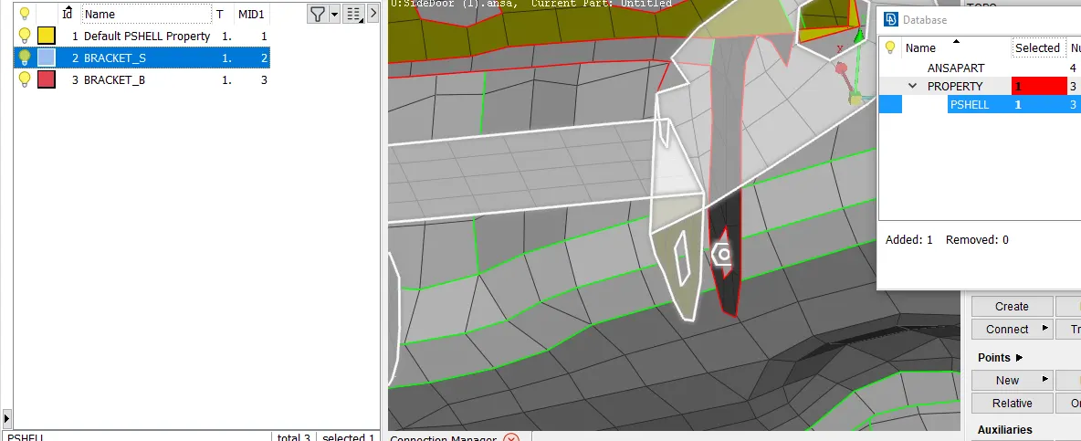
- Manually:
- To perform manually, select RBE2 element (Nastran>Elements>RBE2)
- Select many Nodes, if only the perifery nodes are only required then select the individual nodes.
- then proceed next, and apply degree of freedom if required, and set PID for the for bolt joint.
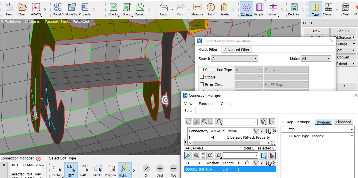
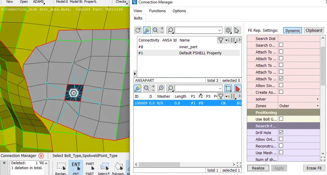
- Automatica:
- Create 3D point at the centre of the hole.
- convert the 3D Point as a bolt (Assembly tab>Convert>3D point>Bolt)
- Open connection Manager and select the Bolt point.
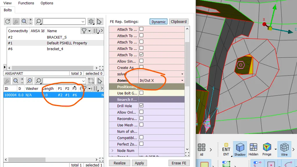
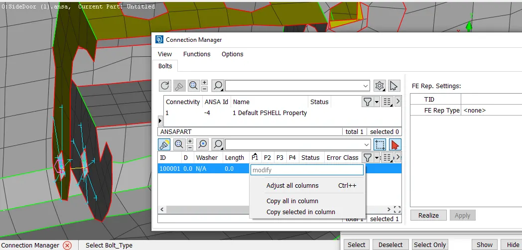
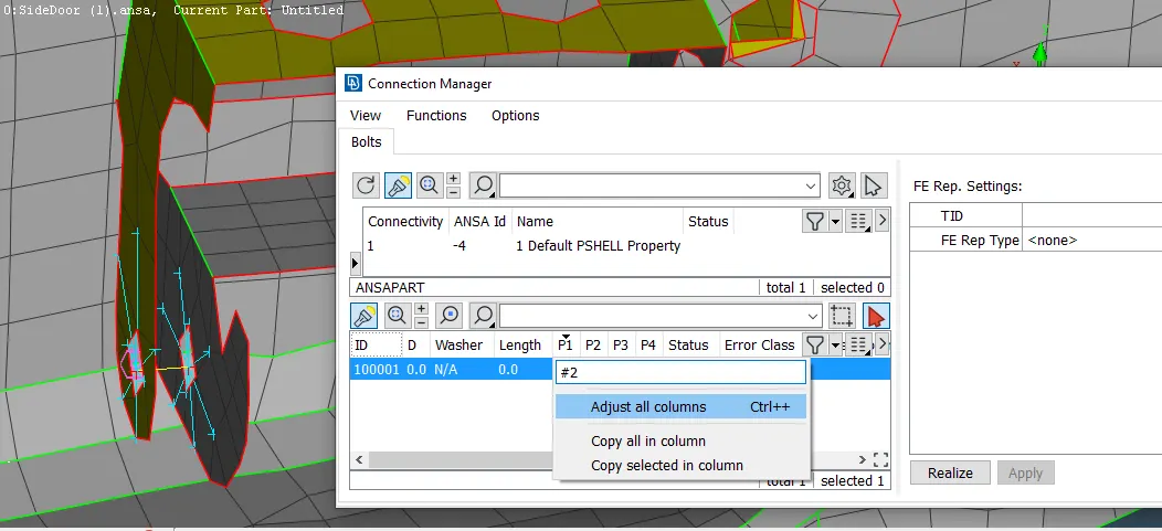
- Select different plate in different section of P1, P2 etc. Max(4 Plate)
- Select the FE rep Type as "RBE2"
- Enter the Search distance and Do, apply and realize.
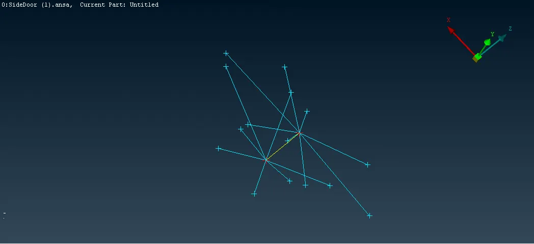
Window damper (Window liner)
- In order to provide the window liner create the curve though FE (Mesh>perimeter>feat2Curve)
- Select the curve and convert it into seam line (Assembly tab>Convert>Curve>Spotline)
- Once the curve converted into seam line, the curve turn into bight pink curve.
- Open connection Manager and select the spotline line.
- Select P1 and P2, and space (S).
- Select the FE rep Type as "RBE3-CBUSH-RBE3"
- Enter the Search distance and set CBUSH PID.
- Do, apply and realize.
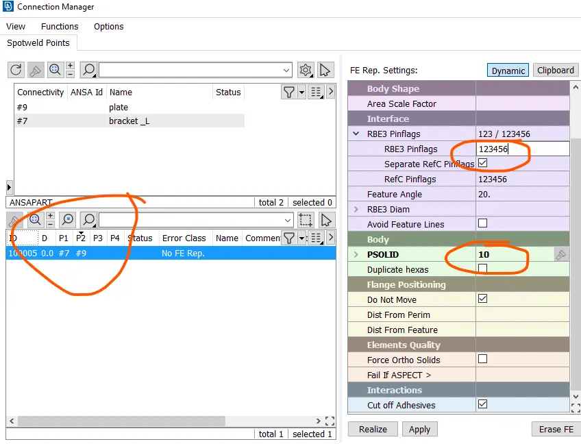
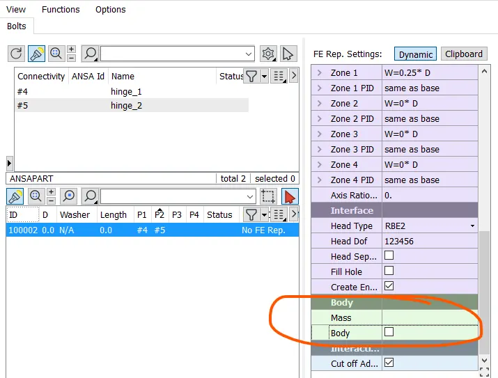
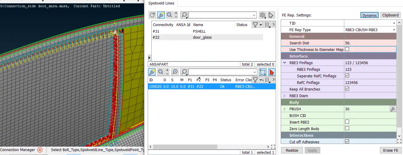
- Perfrom the same step on all the 4 side, and the small fixed glass.
- Once done, Re-orent the CBUSH co-ordinate with the golbel co-ordinate system, by performing modify option.
Revit joint/Spot Weld
It is very similar to bolt connection
- Create 3D point at the centre of the element or edge centre.
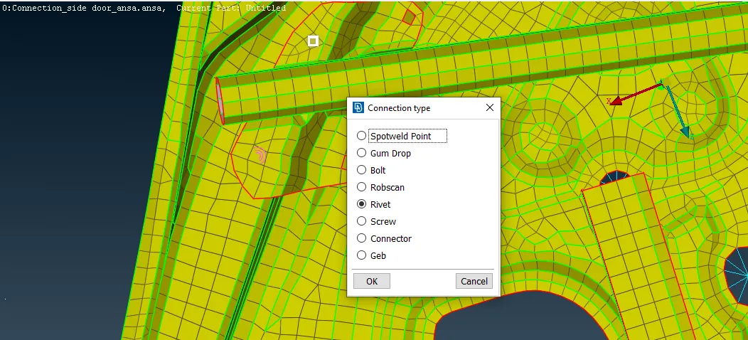
- convert the 3D Point as a bolt (Assembly tab>Convert>3D point>Revit/Spotweld Point)
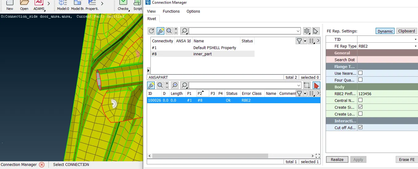
- Open connection Manager and select the point.
- Select different plate in different section of P1, P2 etc. Max(4 Plate)
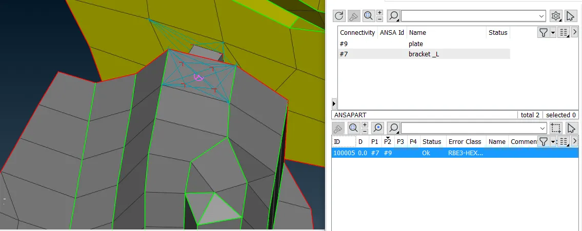
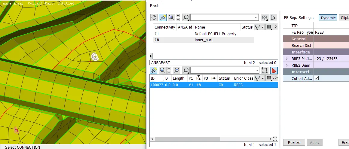
- Select the FE rep Type as "RBE3-HEXA-RBE3" for Spot weld and "RBE2" for Revit
- Enter the Search distance and Do, apply and realize.
- Spot Weld
- Revit Joint
Result:
- All the component are assigned with different PID
- Assembly of the component are done based on suitable connections
Learning outcome:
- creating connection automatic and manually
- RBE2,RBE3, window linear, seam weld, revit and spot weld were learned during the project.
Concultion:
- Differernt PID are assigned to different componet and suitable connections are use to connect the components.