Week 2 Bevel Gear Challenge
'Grid Dependency Test', Grid Independency Test' and 'Mesh Refinement Test', are the synonyms and they all mean the same. While performing Finite Element Analysis, one of the most common question is finite element mesh quality. How can one know if the mesh is good enough for the analysis, Mesh density is a significant metric used to control accuracy? Assuming no singularities are present, a high-density mesh will produce result with high accuracy. However, if a mesh is too dense, it will required a large amount of computer memory and long run time, especially for multiple iteration run that are typically of nonlinear and transient analyses.
The most fundamental method of checking the qualities to refine a mesh until a critical result such as Equivalent stress does not change significantly with each refinement. This is grid dependency test, where, analysis begins with a coarse mesh and it is refined to finer mesh for each run until the result do not change significantly and depend of the grid size anymore. As the grid or mesh size approaches zero, the approximate solution is almost equal to the actual solution. The aim of this test is to find the optimum mesh size for the solution, where it is neither to coerce to produce inaccurate result, neither too fine, where it will consume a lot of computing effort and time.
There are different mesh refinement techniques are used which has advantages and disadvantages and some depends on the experience and technical expertise of the experience and technical expertise of the FEA analyst this techniques include- Reducing the element size, Increasing the element order, Global adoptive mesh refinement, local adoptive mesh refinement, manually adjust the mesh, Time adoptive mesh refinement, wavelength adoptive mesh refinement,
Grid Dependency Test on Bevel Gear.
To perform the test, the simulation is run on three different element sizes-
6mm, 5mm and 4mm. the good practice is to run the simulation at default mesh size and then refine it for the successive runs.
It is good and necessary to remove the unwanted regions and simplify the CAD geometry before the analysis. This ensures that computing resources are conserved, and less time consumed to run the simulation.
The material assigned is structural steel and following are properties for the material.
Structural steel
Density Youngs Modulus Poissons Ratio Yeild Strenght Ultimate Tensile Strength
7850 kg 200 GPa 0.3 250 MPa 460 MPa
Genearal Set-up
First, for all the sake of simlicity, the gear are name as 'small' and 'big' according to their there size. Then, conduct between all the tooth face of the both the gears is defined with following setting-
Type Fricttional
Behavior Symmetric
Formulation Augmented Lagrange
Interface Treatment Adjust to touch
Augmented Lagrange or pure Penalty is preferred for non-linear solid body contact faces.
Then two revolute joint are defined, one for each gear with a connection type of 'Body-to-ground'.
For the analysis settings, following setting are applied-
Number of step 6
Auto- time setting on
Defined by time Time
Initial time step 0.001 s
Maximum time step 0.0005 s
Large-deflection is turned 'on' as prompted during the analysis to overcome convergence issues.
Two joint load are defined. The small gear is given a clockwise rotation with 20 `degree`increament up to 120. The big gear is given a movement in anti-clockwise direction with 100 Nm for each step.
for proper run of simulation improve computational analysis setting
stabilization constant
method Energy
Energy desipation 0.1
Stabilization Force 0.2
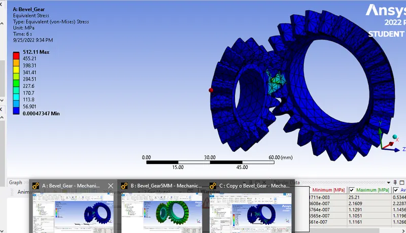
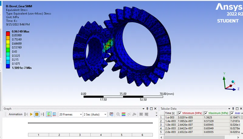
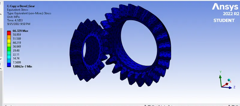
Equivalent Stress
6 MM 5 MM
4 MM
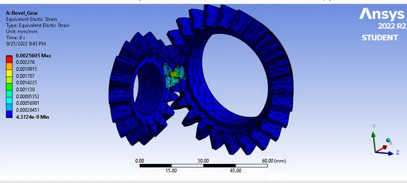
Equivalent strain
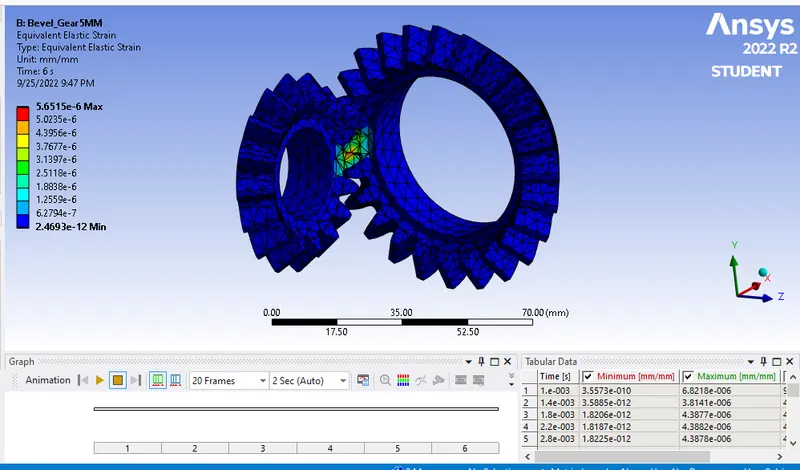
6 MM 5 MM
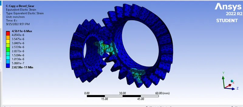
4 MM
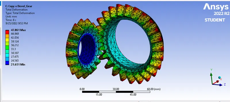
Total Deformation
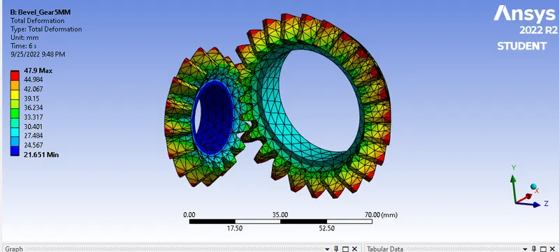
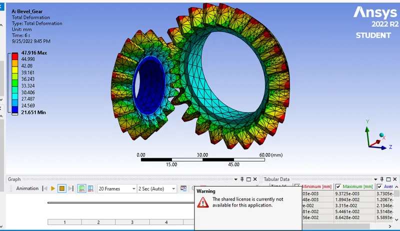
Discussion
the Grid dependency test perform for the three cases, where global mesh size used was 6mm, 5mm and 4mm while the without taken any face sizing in all the cases. The following are the result for the three cases.
Element size Equivalent Stress Equivalent strain Total Deformation
6mm 512.11 MPa max 0.0025605 MM 47.916 max MM
5mm 0.96749 MPa 5.6515e-6 MM 47.90 max MM
4mm 0.96749 MPa 5.6515e-6max MM 47.90 max MM
it is observed that no change is obtained for the Total Deformation for all the cases and remained at 47.9 mm
As the element size was reduced from coerces to fine, it can be observed that the number of Nodes and Elements increase as shown in the following table.
Element size Number of Nodes Elements
6mm 13541 7040
5mm 12268 6238
4mm 15663 8142
as expected from the Grid dependency test, as the mesh was change from coerce to fine, the accuracy in the improve, it can be seen from the first table that there was a significant improvement in the result for both equivalent stress and equivalent strain. from 6mm to 5mm the huge percentage of improvement are observed for equivalent strain and also for Equivalent stress.
it is also observed that when the mesh was made finer from 5mm to 4mm, no change in Equivalent stress result and equivalent strain result was observed, which mean that Grid Independency has reached and further the result are not dependent on grid size or element size anymore and further reducing element size is unnecessary.
If the mesh size further reduce, it will only increase computational time. Therefore, it can be said that the optimal mesh size is 4mm.
Animation are attached.