Week 1 Stress Concentration on a Plate with hole
Case:1 Design a Plate with Hole with increase in thickness upto 30 mm.
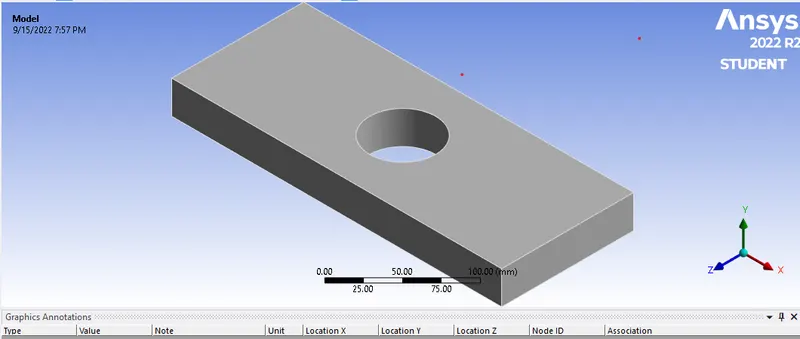
The 3D model of the plate is as shown in below image.
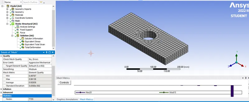
A mesh matric that identifies element according to there quantity was employed and it can be seen the element of the lowest quantity are minimul most of the element have very high quality in the range of ----
The mesh model is as shown in image below.
CASE:2 Plate with hole, using the same model from the task 1 with increasing hole thickness upto 30 mm. include two smaller hole of dimeter 30 mm and distance 90 mm from centre hole.
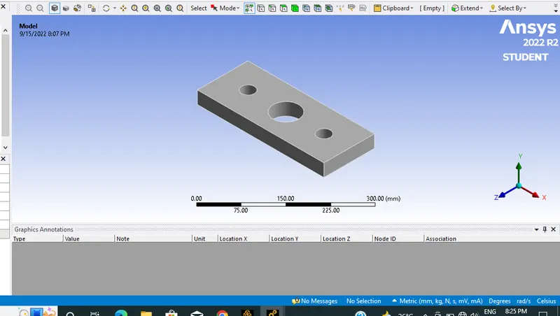
The 3D model of the plate is as shown in below image.
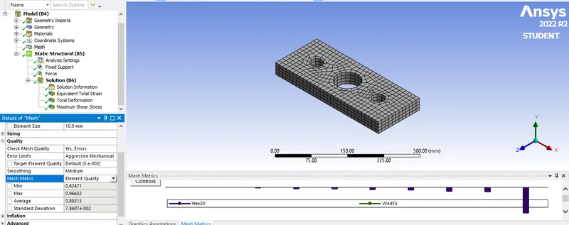
A mesh matric that identifies element according to there quantity was employed and it can be seen the element of the lowest quantity are minimul most of the element have very high quality in the range of ----
The mesh model is as shown in image below.
The fix support is applied on the one side of the model and Tensile load of 500 N are applied on the other side of the model, the simulation is succesfuly run and result are obtained.
RESULT:
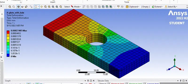
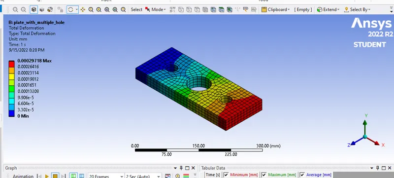
The Total Deformation for the model compared.
minimum (Mpa) maximum (Mpa)
1. 0 0.000274
2. 0 0.000297
The total deformation are shown in below image.
The Equivalent Stress for the model compared.
minimum (Mpa) maximum (Mpa)
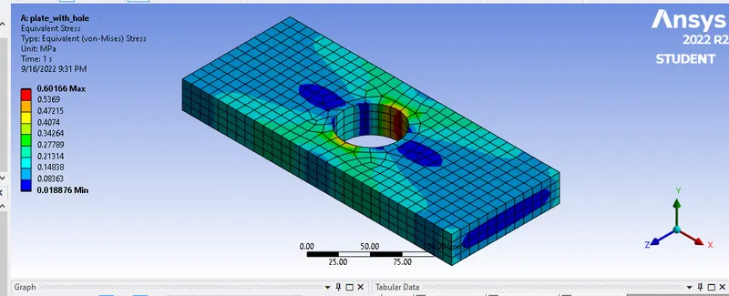
1 0.018876 0.60166
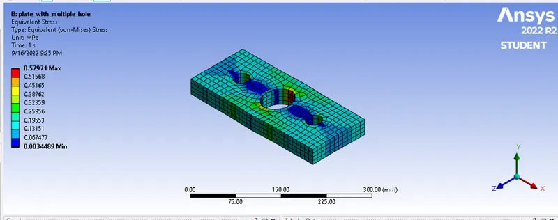
2 0.00344 0.57971
The Equivalent Stress for the model can be plotted below.
CONCLUSION:
The analysis was run succesfully within the limit of the academic licence, the simulation for the 2 case were examined. the mesh size that could be use in both case different significally as a result of the appearance of the two hole which result in lesser material.
on the comparison of the total deformation experienced by the model in the 2 case only a slight difference in the average value is evident of the order 0.00002 MPa with case 2 having a higher value.
on the comparison of stress experience by the model in the 2 case a difference of 0.17 MPa is evidence in the average equivalent stress.
On the basis of there result from an analysis point of view, case 2 can be chosen because of the stress undergoes by it an application of the same tensile force is lesser than its counter part an also because the difference in deformation value are also very small.
From a manufacturing point of view case 1 can be chosen because the work that has to be done on the model is lessor when compered to case 2 and there is not much improvement in performance.