Week 2 Railwheel and Track
PROCEDURE
After inserting the joint we need to generate mesh of element size 35 mm.
We need to define load as per required for simulation. ( Bearing load and joint displacement load )
All this load should be given in 5 step such that rotation will takes place in step and result that is evaluated will be clear.
For the first step leave the auto time step to be program control and solve type to be direct. Switch on the large deflection and all the output control also needed to be switched on.
For 2 to 5 step set auto time step set to ON and step control to be define by time.carry over the time step minimum and maximum time step should be 1e-0.003s and 0.1 s respectively.
Now apply bearing load of 500000 N and also 100000 N in Negative Y Direction.
Insert displacement in. -Z Direction till haft the strack.
Now finally cleack on right click on solution and insert al the things we need to evaluate like
CASE 1:
Multiply the bearing load by 5 times and compare the results with the load of 100000 N.
Stress Equivalent
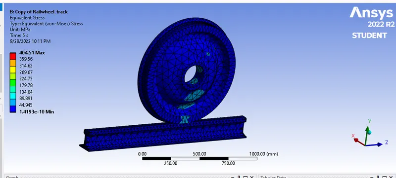
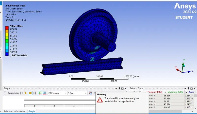
Railwheel track 500000N Railwheel track 100000N
Strain Equivalent
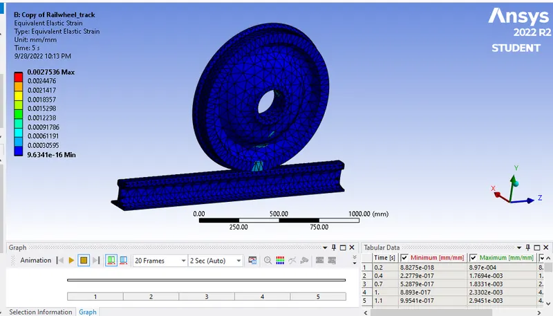
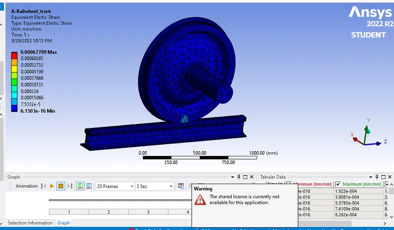
Railwheel track 500000N Railwheel track 100000 N
Total Deformation
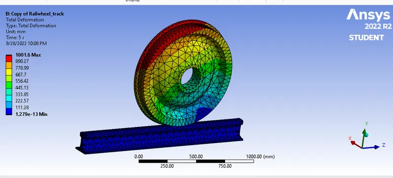
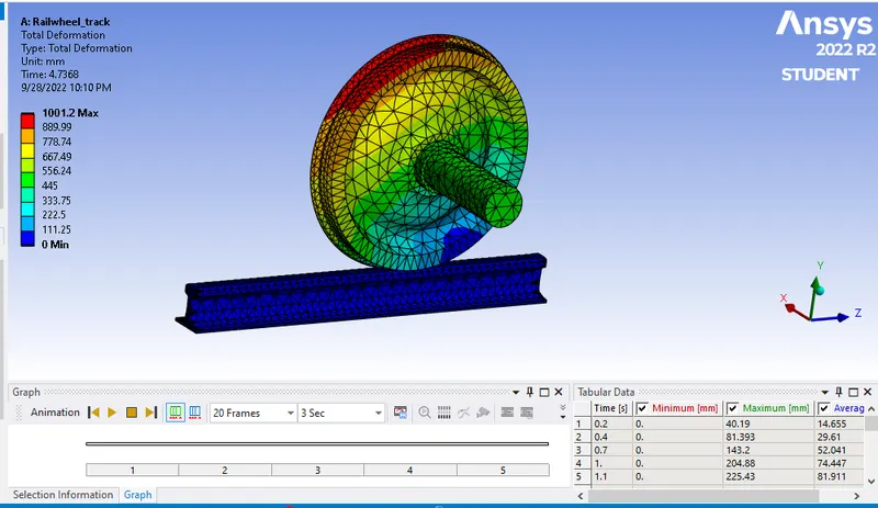
Railwheel track 500000N Railwheel track 100000N
LIFE UNDER BOTH LOAD\Futigue LIfe
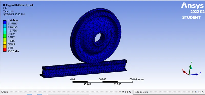
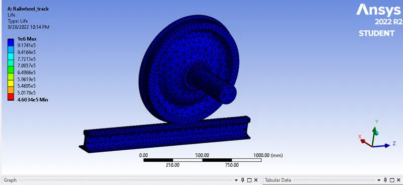
Railwheel track 500000N Railwheel track 100000N
Conclusion:-
We performed the RAILWHEEL AND TRACK simulation using ANSYS WORKBENCH and obtained the following results.
Case. A. B
Load. 100000 N 500000 N
Max stress 98.633 MPa 404.51 MPa
Min stress 1.0655e-10 MPa 1.4193e-10 MPa
Max Deformation 1001.2 mm 1001.6 mm
Min Deformation 0 1.279e-13mm
Case 2:
Bearing load :- 100000 N
User Define Result and Total Deformation results.
Picture as per given bellow.