Week-7 : Converting a detailed engine model to a FRM model
Aim:
To understand the concept of converting high-fidelity model to fast running model (FRM) and also building FRM model using builder approach.
Objective:
To understand the concept of converting Engine Model to Fast Running Model (FRM) from Tutorial-9.
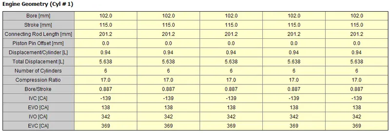
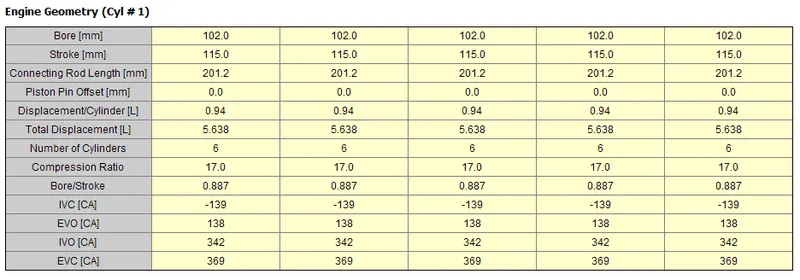
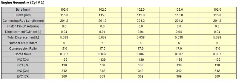
Building FRM Model for following configuration using FRM builder approach
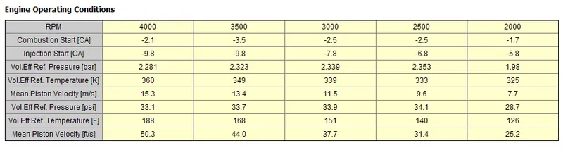
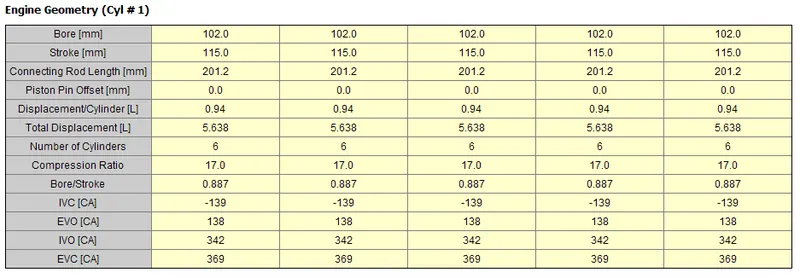
- Bore 102 mm stroke 115 mm CR 17
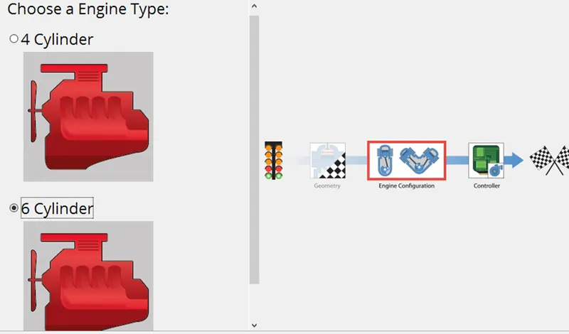
- No of cylinder 6
- CI engine
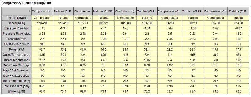
- Twin Scroll Turbine
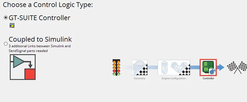
- GT Controller
Description:
The Fast Running Engine Models are designed in such a way that the simulations run faster. Generally we use detail modeling for capturing the wave dynamics that occurs in the intake and exhaust system. In order to capture those waves we need to have a very detailed model to capture the physics. Whereas if the speed of the simulation running is necessary there we use use Fast Running Model. In GT-Power we follow two approaches i.e. Mean Value and FRM model. When the simulation speed is the main criteria the detailed model can be simplified into FRM's using the standard conversion process. The FRM Models are fully physical and dynamic in nature and also designed to run fast. The mean-value approach is no feasible as we cannot capture the in cylinder pressures and also it requires more data and statistics is involved. Where as in fast running approach we can retain the physical approach for the model and also get good accuracy. The FRM's are able to achieve such fast run times by two means i.e.(a)Increasing the simulation time step size (b)Decreasing the number of calculations per time step.
In FRM model there are two approaches i.e. FRM Converter & FRM Builder. The FRM converter helps to convert the detailed model to FRM, and in FRM builder the FRM is built from scratch using FRM Tool.
Tutorial-9 (FRM):
This tutorial covers the process of converting detailed, high fidelity engine model into a real time fast running model.
Simulation model:
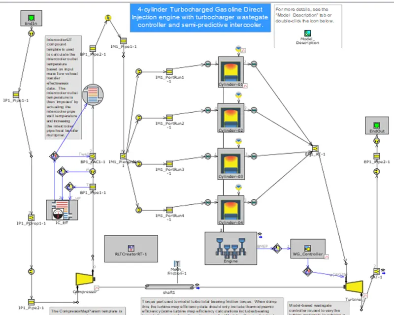
The model is 4 cylinder 4 stroke turbocharged direct injection gasoline engine. Turbine waste gate is being controlled to achieve target BMEP.
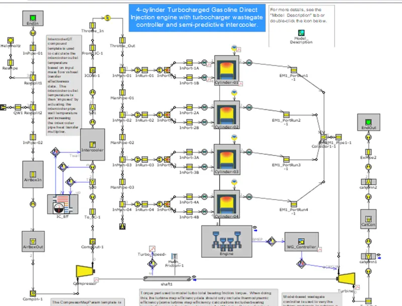
FRM conversion steps:
Exhaust manifold:
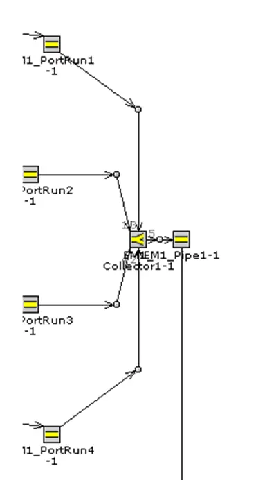
Intake manifold:
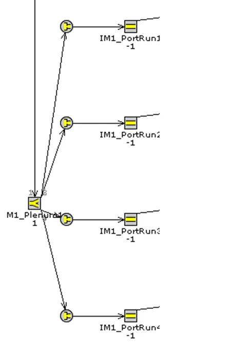
Compressor Intake and outlet:
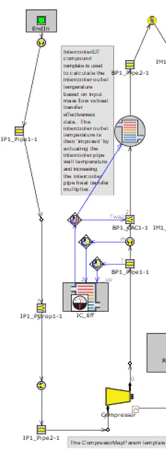
Exhaust port:
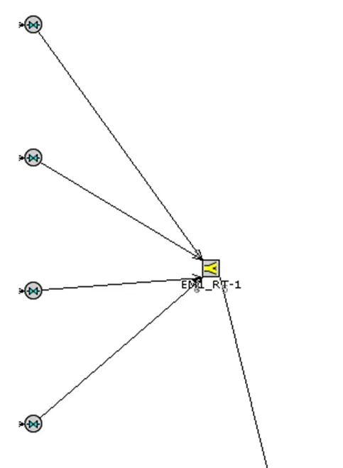
Real time solver:
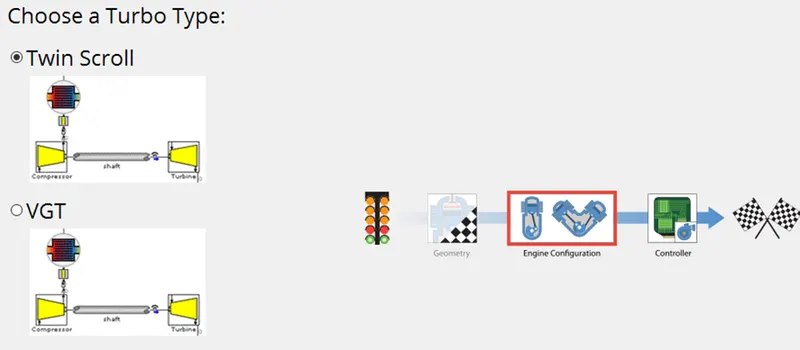
FRM model builder:
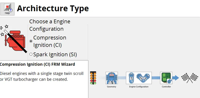
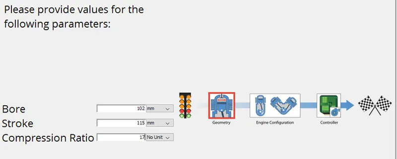
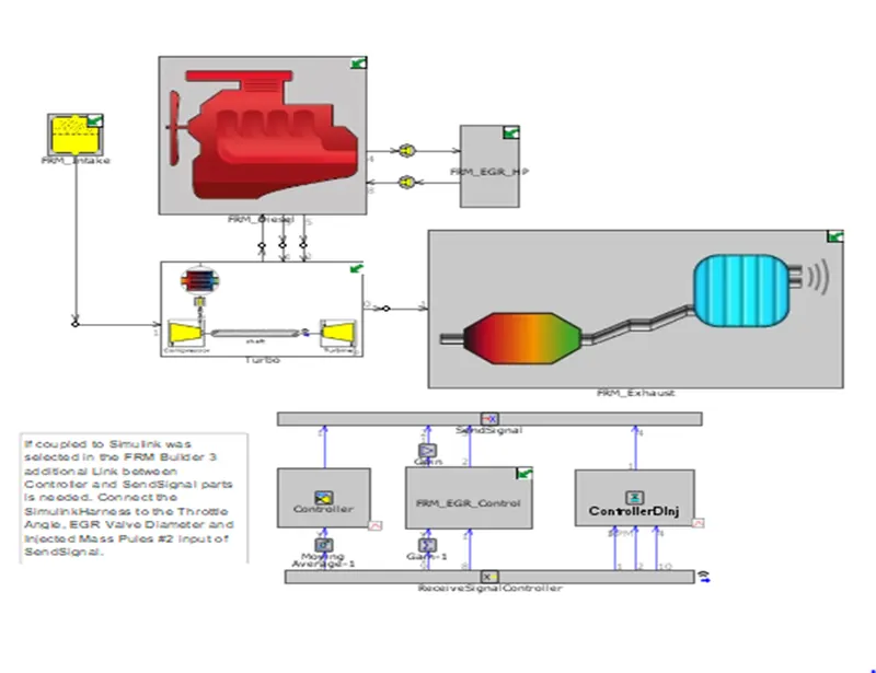
FRM diesel:
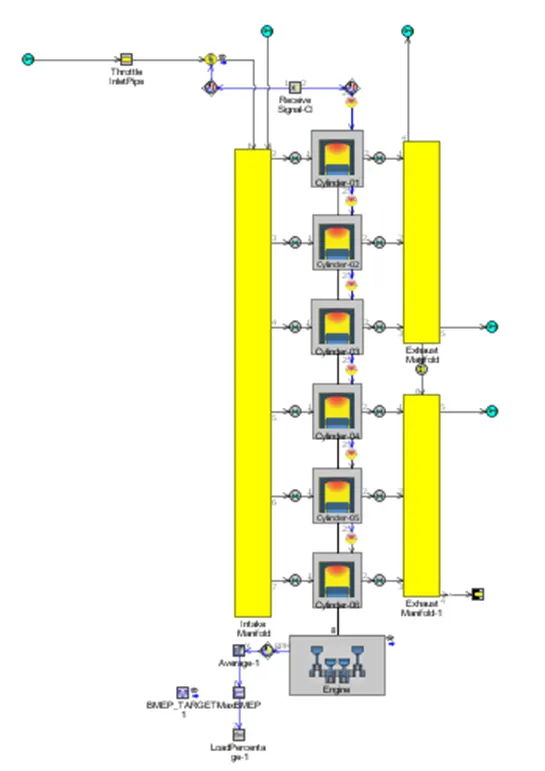
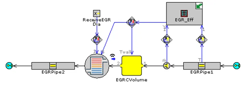
FRM EGR HP:
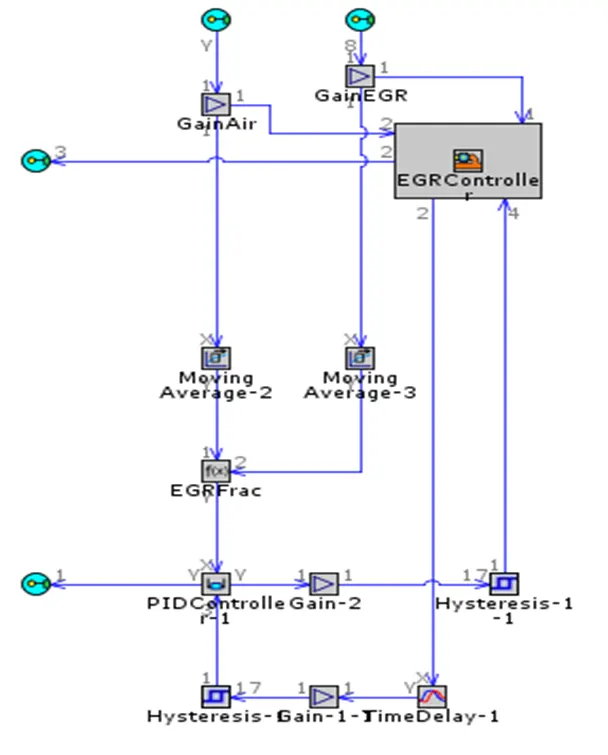
FRM EGR Control:
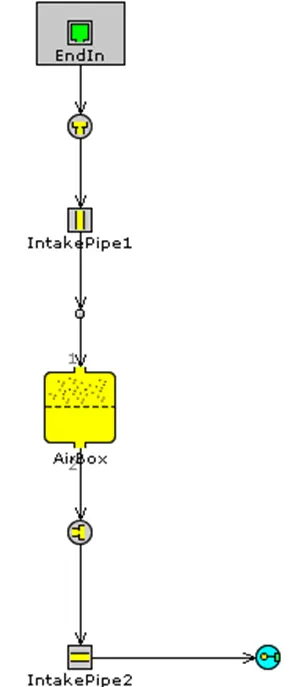
FRM Intake:
FRM Exhaust:
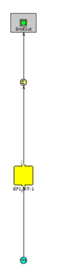
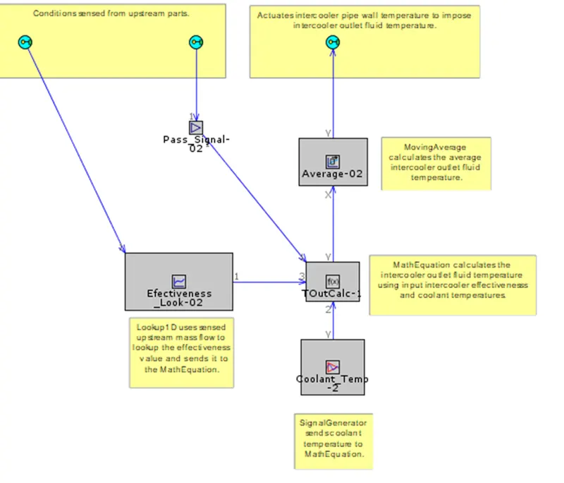
IC Effectiveness:
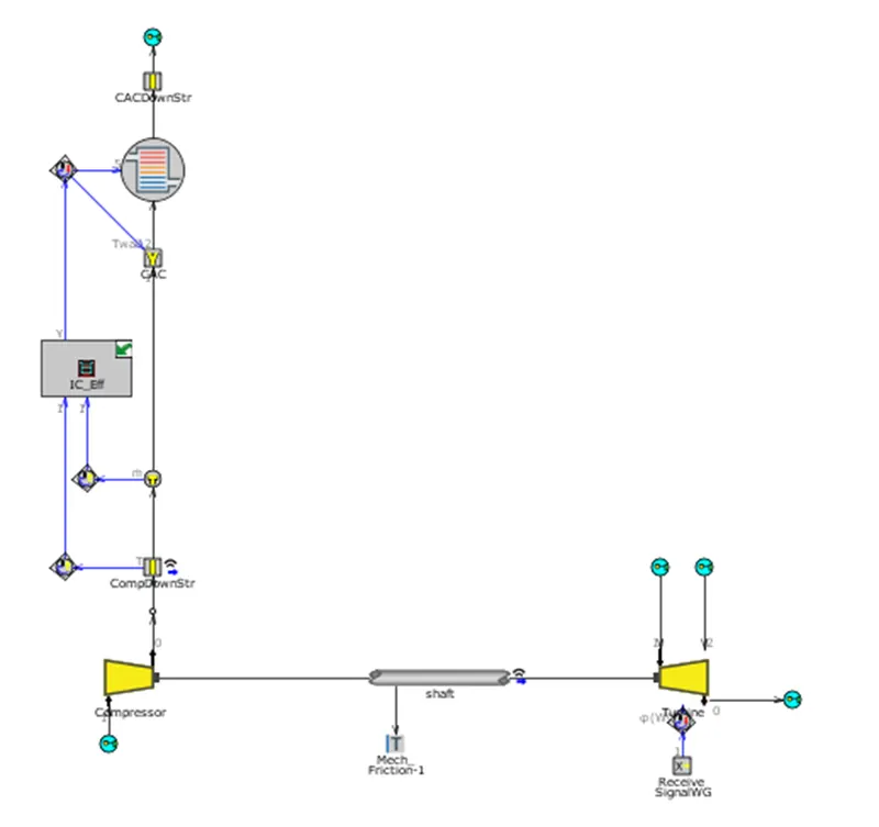
Turbo:
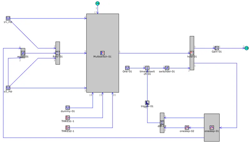
Hysteresis loop:
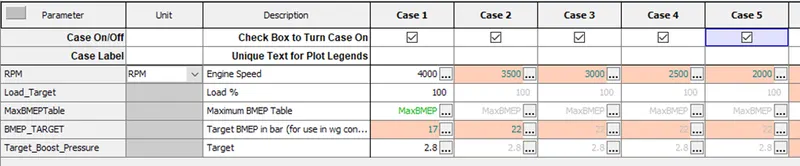
Case 1:
Load target 100%
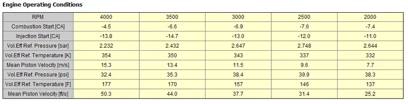
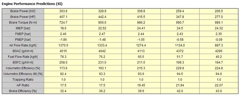
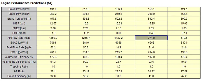
Results:
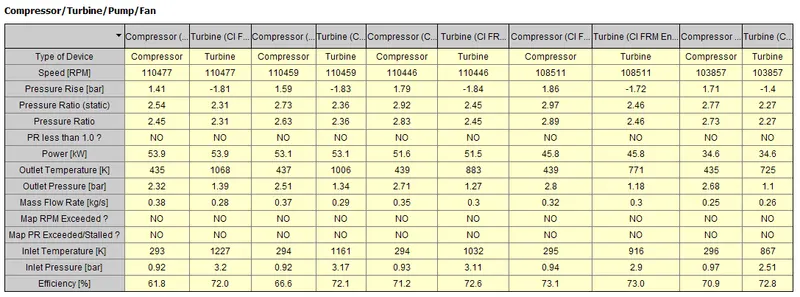
Case 2:
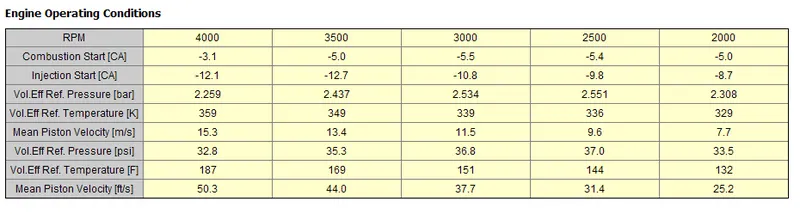
Load target 80%
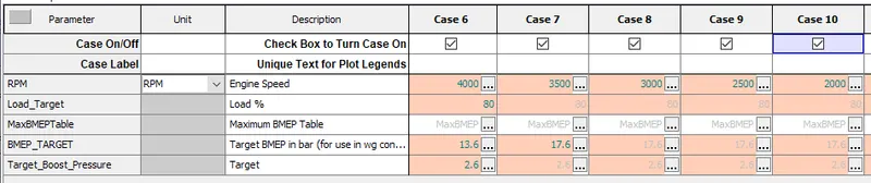
Results:
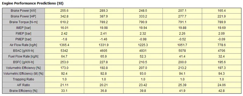
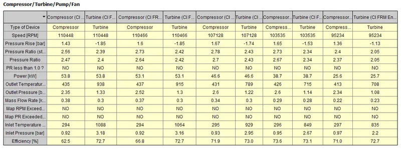
Case 3:
Load target 60%
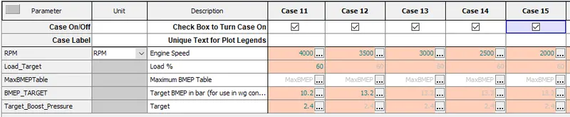
Results:
Case 4:
Load target 40%

Results:
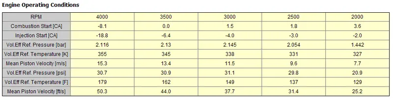
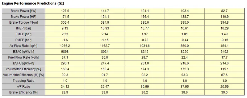
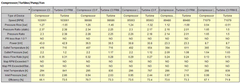
Conclusion:
- With FRM model builder approach the specific engine design is modelled successfully.
- GT post simulation results shows that with low target BMEP and low rpm level falls on the best design efficiency region of the compressor map.
- FRM model reduces the computational time drastically as compared to normal simulation run time model