Week-7 : Converting a detailed engine model to a FRM model
1.Explore tutorial number 9 and write a detailed report (50 marks)
Building a Fast Running Engine Model (FRM)
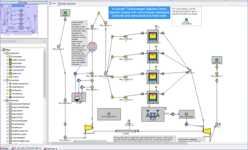
Launch GT-ISE and open the file SI_4cyl_GDI_Turbo-WOT.gtm from 'File' -> 'Examples' -> 'Engine_1D_Gas_Exchange_Combustion' -> 'Gasoline' -> 'SI_4cyl_GDI_Turbo'. This is the starting model for this tutorial.
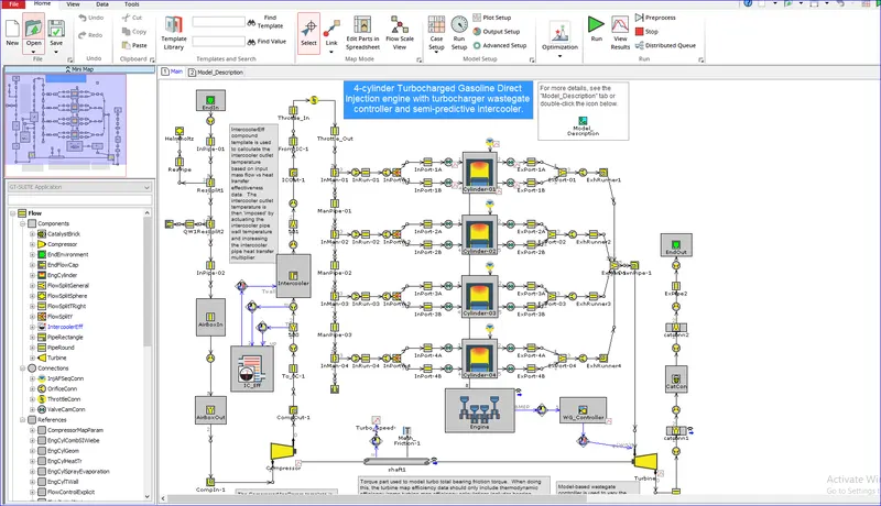

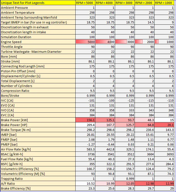
below is the 5 test cases which were run to validate the efficacy of the FRM with the complete models
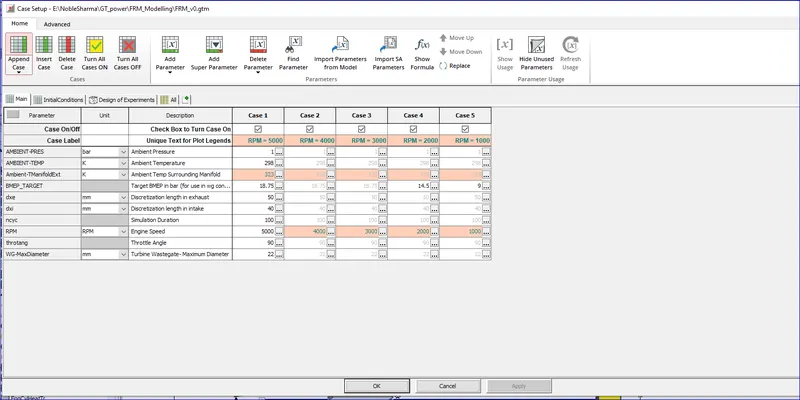
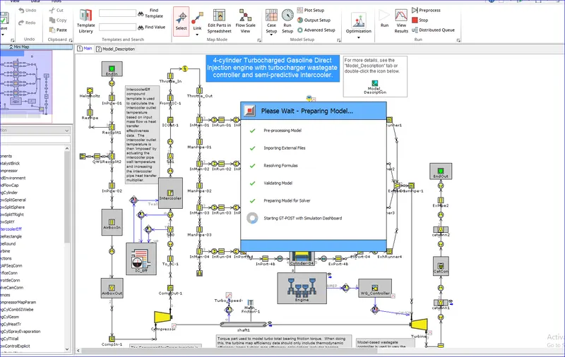
The values obtained before the FRM model for the quanitative analyis are:

Steps involved in making an FRm from the complete model:
We need to check those systems with higher courant number or higher time steps.
Timestep Restricting Parts, Number of Subvolumes
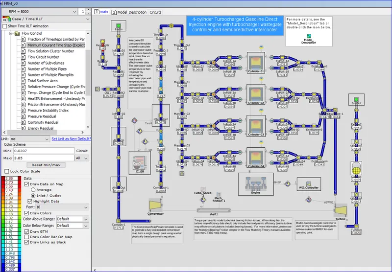
To get an overview of parts that potentially limit the timestep open the SI_4cyl_GDI_Turbo.gdx result file in GT-POST. The file should be in the same directory as the model.
- Select RLT Contour Map -> Pipes/FlowSplits -> Flow Control -> "Minimum Courant Time Step (Explicit Circuits Only)". This will give an overview of all parts and the associated courant number. The lower the value, the more likely the part will limit the timestep
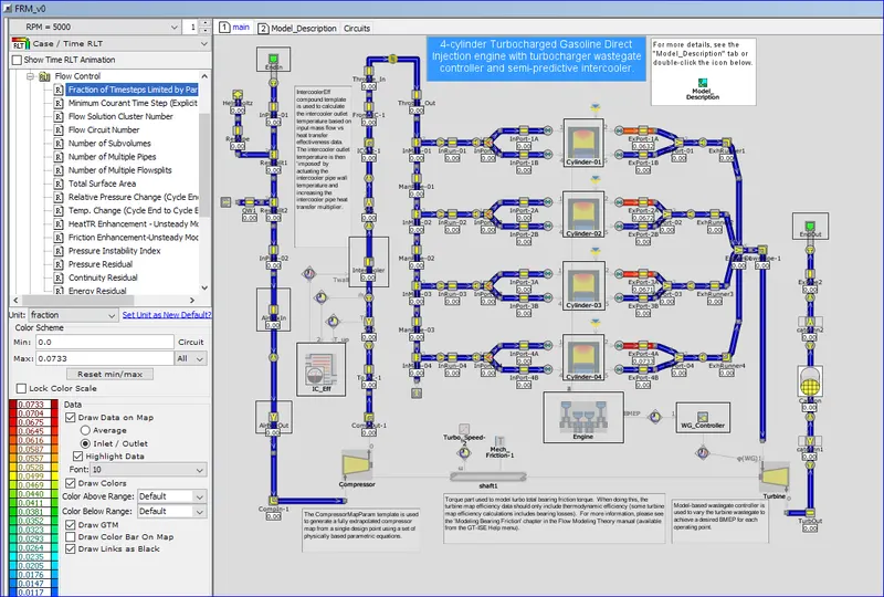
Another option to determine timestep limiting parts is to select "Fraction of Timesteps Limited by Part" directly above "Minimum Courant Time Step (Explicit Circuits Only)". In contrast to the courant number only parts that limit the time step will be displayed.
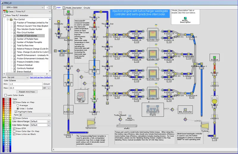
Launch FRM Tags
With the high-fidelity engine model open in GT-ISE, go to the Tools tab and click on 'FRM Tags'. The model has already been tagged. You can select the individual subsystem and the parts are getting highlighted on the map
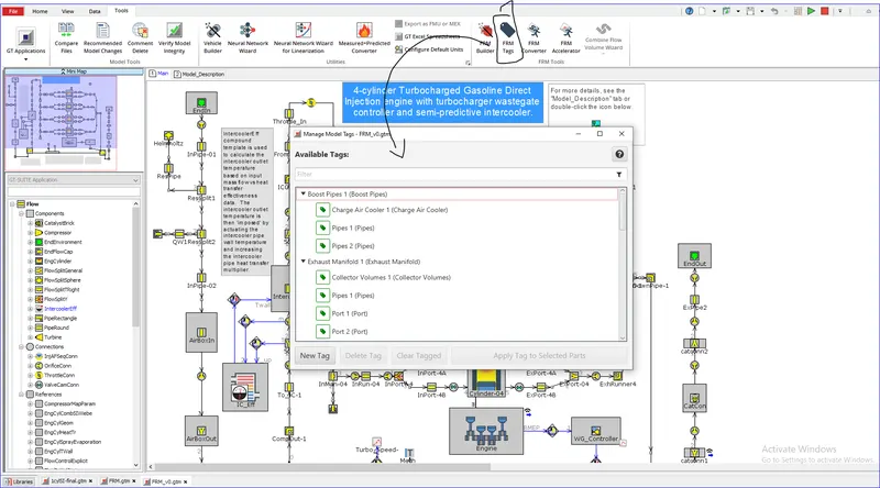
Launch the FRM Converter
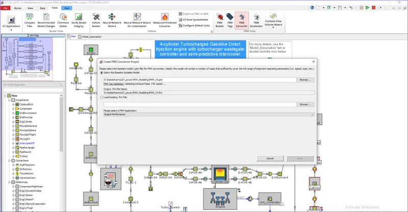
The GT-SUITE FRM Converter is a tool that will track the FRM Conversion process, organize all model files automatically within subdirectories, and provide result comparisons of key RLTs throughout the conversion process. The process information is stored in a *.frm file which can be saved and reloaded at any time to review the process or to continue where you left off.
With the high-fidelity engine model open in GT-ISE, go to the Tools tab and click on 'FRM Converter'. This will prompt you to create an FRM Conversion Project. It will validate the tagged subsystems and report if the validation is successful. Confirm that the correct model is specified in "Select the Baseline Detailed Model" per below, then click Next.
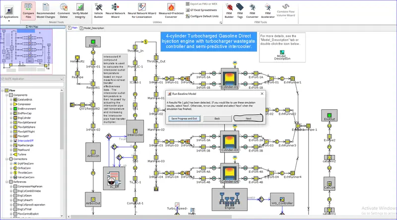
Adding an absolte tolerance critetia on the the bsfc:
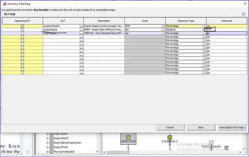
Step 1: Exhaust Manifold
It is now time to start simplifying the first subsystem of the model. It is most efficient to start by simplifying the subsystem thatis currently restricting the time step.
- For high-fidelity models, this is almost always the exhaust manifold where the highest gas velocities occur, which in turn restricts the time step. For Step Name, type "Exhaust Manifold". Select Exhaust Manifold 1 from the Tagged Subsystems list
-
Before we apply simplifications to the exhaust manifold, the Maximum Time Step limit of 1 crank angle degree will be removed.
-
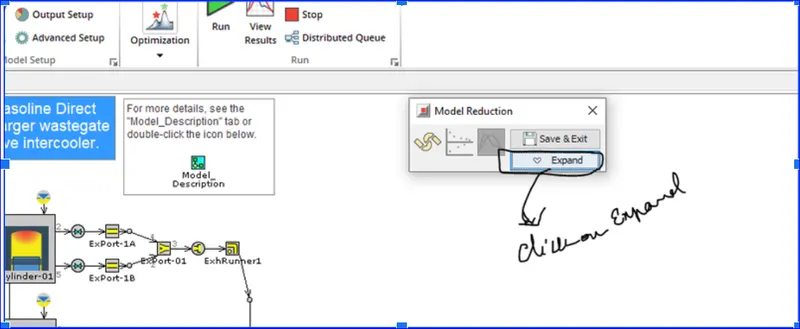
Click "Collapse" at the top-left of the FRM Converter to collapse it into a smaller, more manageable dialog.
-
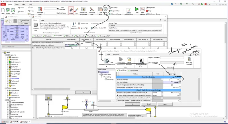
Then, from the "Home" tab, click on "Run Setup" and go into the "FlowControl" folder, then double-click on the "ExplicitControl" green text within the "Time Step and Solution Control Object" attribute to edit the ExplicitControl reference object. Set "Maximum Time Step" to 720, then click "OK", and "OK" again to close Run Setup.
- Make sure that the "Apply Smart Calibration Settings" check box is selected
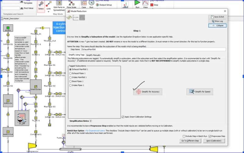
- If accuracy is of higher importance than run-time, choose the "Simplify for Accuracy" option. This will combine the Exhaust Ports/Runners together, and left separate from the manifold volumes.
- If a real-time capable model is required choose "Simplify for Speed". In this case the Ports, Runners, and Manifold volumes will be combined together at once.
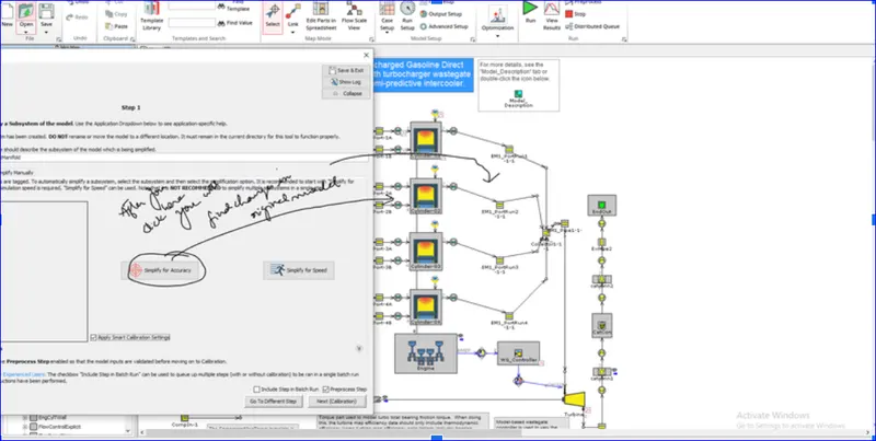
Accuracy is our focus for now: ==> option is to select the simplify for the Accuracy
- proceed by clicking on the “Simplify for Accuracy” button.
- Clicking on the "Simplify Manually” tab will allow to manually simplify geometry for parts that were not tagged or where a different combination of volumes is desired.
- The Discretization Length in the pipe parts will be overwritten with an automatically created parameter called [dxe_FRM]. Its value will be set to 300mm.

- Port Heat Transfer dominates vs. Runner Heat Transfer, therefore a parameter for the heat transfer multiplier called [HTM_Exhaust_Manifold_1_Step_1] will be automatically created in all port/runner pipes Thermal tab
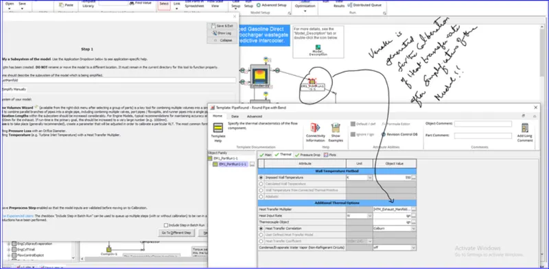
This parameter will be used to calibrate heat transfer in the combined volume to assure the Turbine Inlet Temperature is maintained
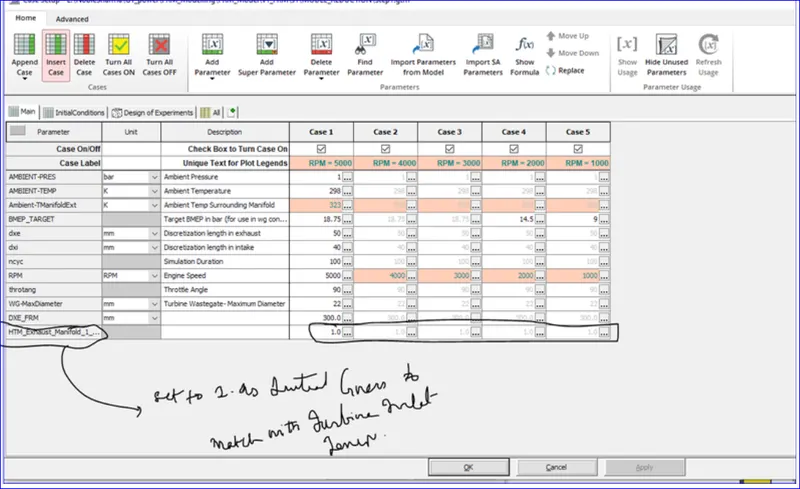
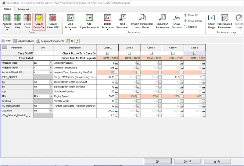
- To check the created parameters, launch Case Setup from the toolbar. Note that this Heat Transfer Multiplier parameter will be calibrated to match the Turbine Inlet Temperature, and so a value of 1 is simply used as an initial guess.
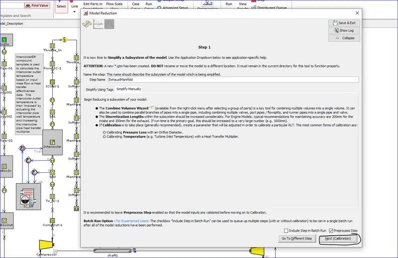
- Click "Next (Calibration)". Note that by default, the simplified model will be preprocessed in order to assure it is ready to run before setting up calibration. Once preprocessing is complete, close the preprocessing window to progress to the Calibration page.
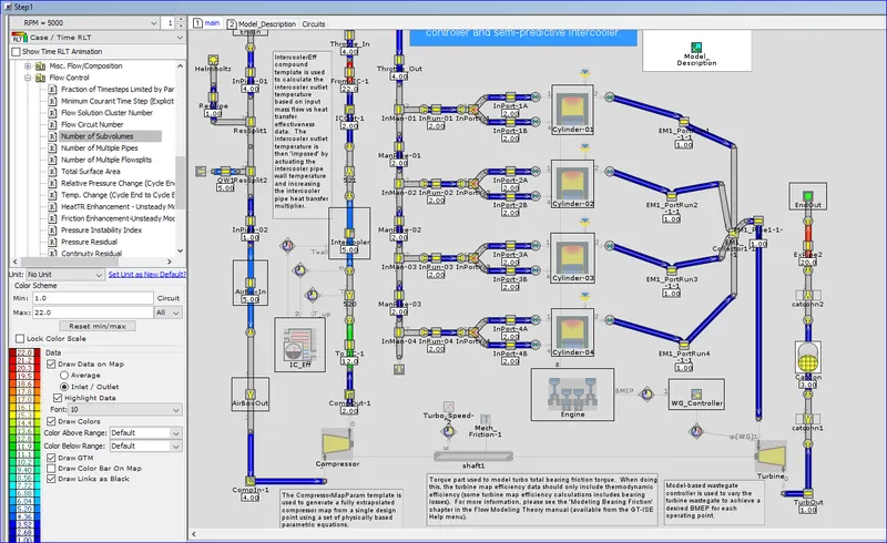
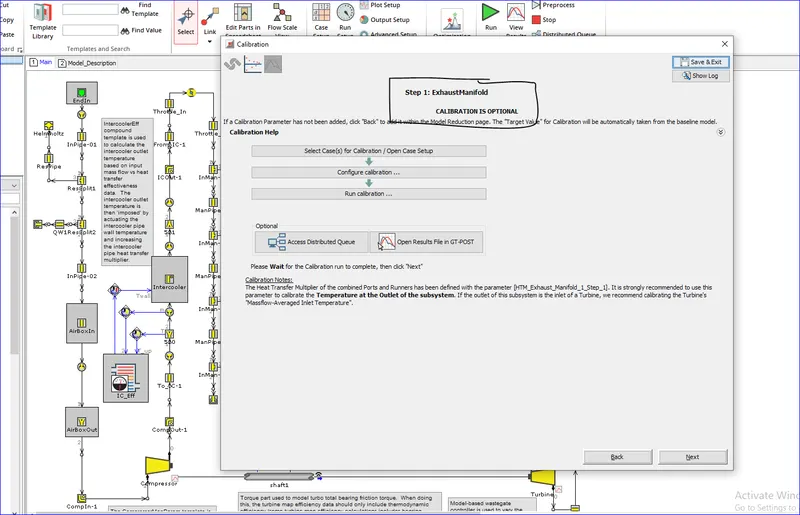
In the Calibration page, click "Select Case(s) for Calibration / Open Case Setup". For this conversion, we will only calibrate for the highest speed case. So, turn Off all cases except Case 1, then click OK. If additional accuracy is desired, and if the extra computational time of calibrating additional cases is acceptable, the calibration could be performed across all cases.
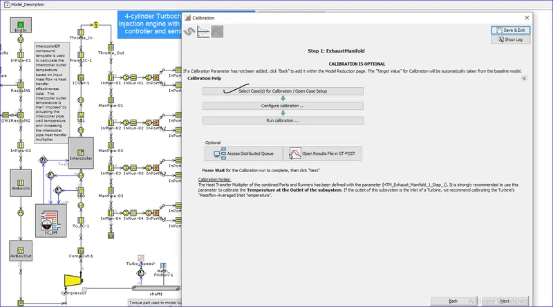
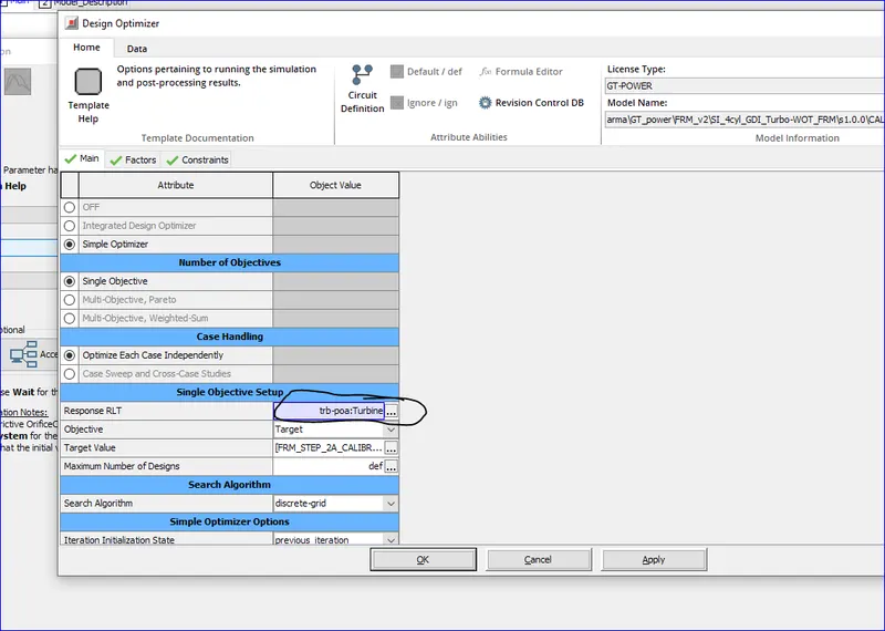
Click "Configure Calibration" to open up the Design Optimizer settings. Make sure "Target" is selected for "Objective". Use the value selector for Response RLT and browse to and select "Massflow Averaged Inlet Temperature" from the Turbine part, as shown below
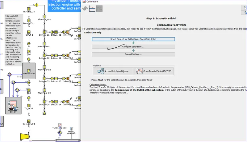
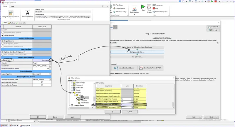
Notice how the Target Value for the calibration is pre-defined as a parameter. The values for this parameter are taken automatically from the results of the baseline, high-fidelity model. This will assure that the calibration will try to match the results from baseline model.
Go into the "Factors " tab to define the factor along with the Lower and Upper values for the Range, and finally the Resolution.
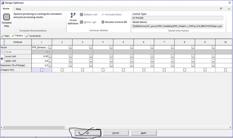
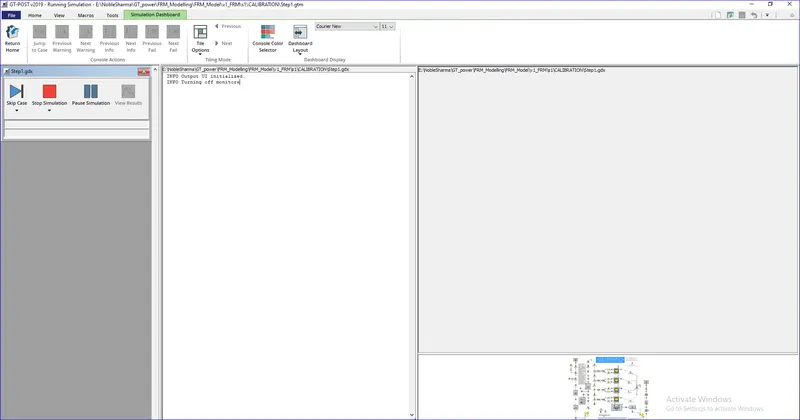
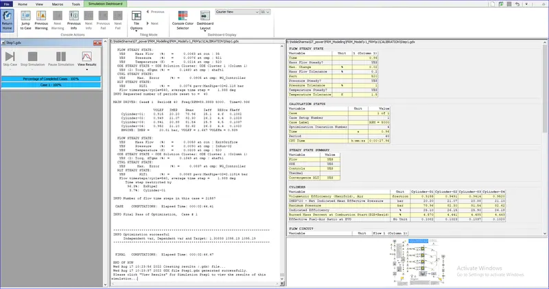
Click OK in the Design Optimizer dialog, then finally click "Run calibration…" from within the FRM Converter and run the simulation.
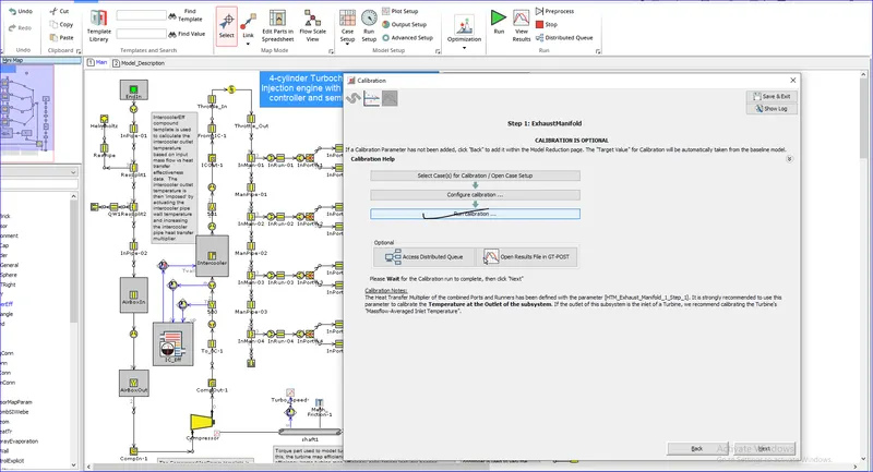
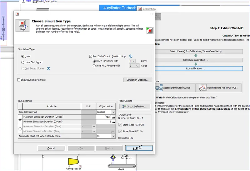
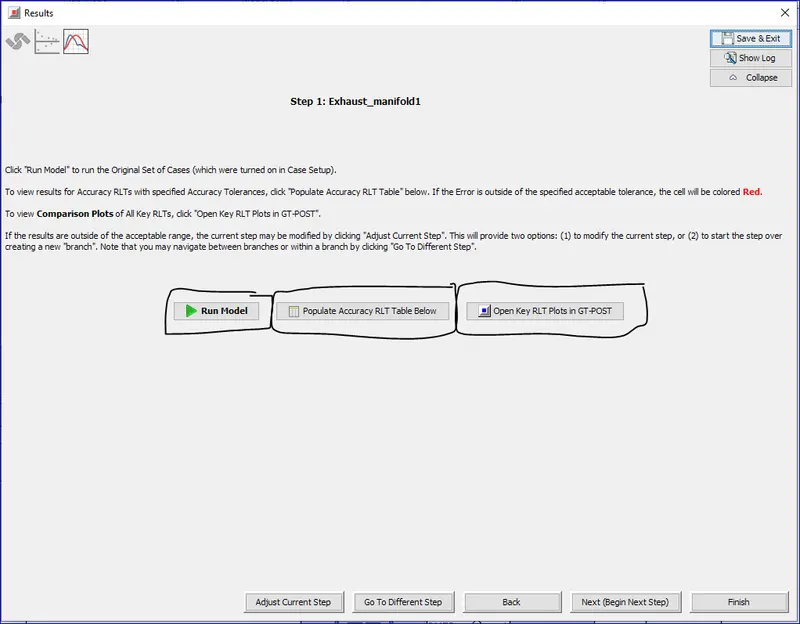
Once the optimization run is completed, close the simulation window and then click "Next" to go to the Results page. Note that the optimized parameter value has been automatically placed back in the model, and all of the original cases turned back On. Therefore, from the Results page, click "Run Model" to run the complete set of cases using the optimized value.
Step 2: Exhaust Pipes


- Once in the Combine Flow Volumes wizard, keep "Combine flow volumes to Flowsplit" selected and click "Next" through the wizard until the last page, "Object Attribute Definition and Object Naming".
- Select "EP1_PDrop1-1" at the top of the dialog, then set the object name to "CAT". The Thermal tab shows that inputs are missing. We are dealing with it later, click "Finish".
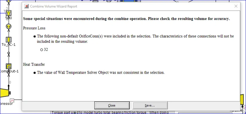
- Hit Close in the "Combine Volume Wizard Report".
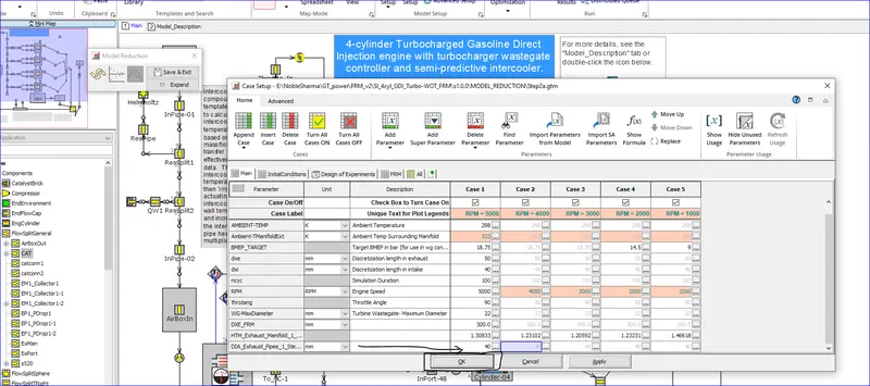
Lastly, we need to Open Case Setup and set the value of [DIA_Exhaust_Pipes_1_Step_2] to 40 mm. This is only an initial guess, and will be used to calibrate the Turbine Outlet Pressure. In the FRM Converter, click "Next (Set Calibration)".


Step 3: Intake Manifold
Name the step "Intake Manifold". Select Intake Manifold 1 from the Tagged Subsystems list. Click on "Simplify for Accuracy". Click "Yes" on the Delete Part dialog; this will be handled later. Collapse the FRM Converter to provide space to work in the model map
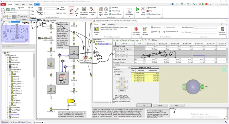
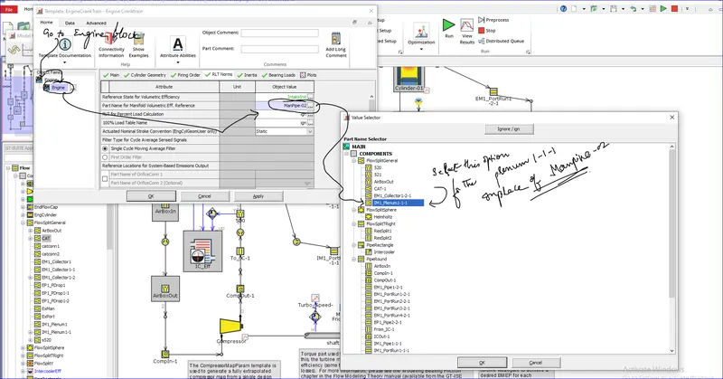
- To resolve the "Delete Part" warning that was previously displayed, double-click on the EngineCrankTrain, go to the "RLT Norms" folder, and change the value of the attribute "Part Name for Manifold Volumetric Eff. Reference" to "IM1_Plenum1-1".
- Then, go into "Run Setup" -> "ConvergenceRLT" folder and change the first RLT Variable to "pav:IM1_Plenum1-1".

completing all the steps from step 1 to step 7 e
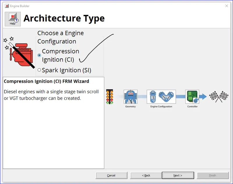
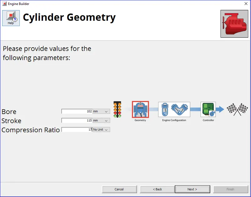
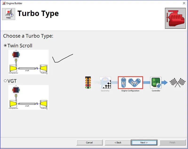
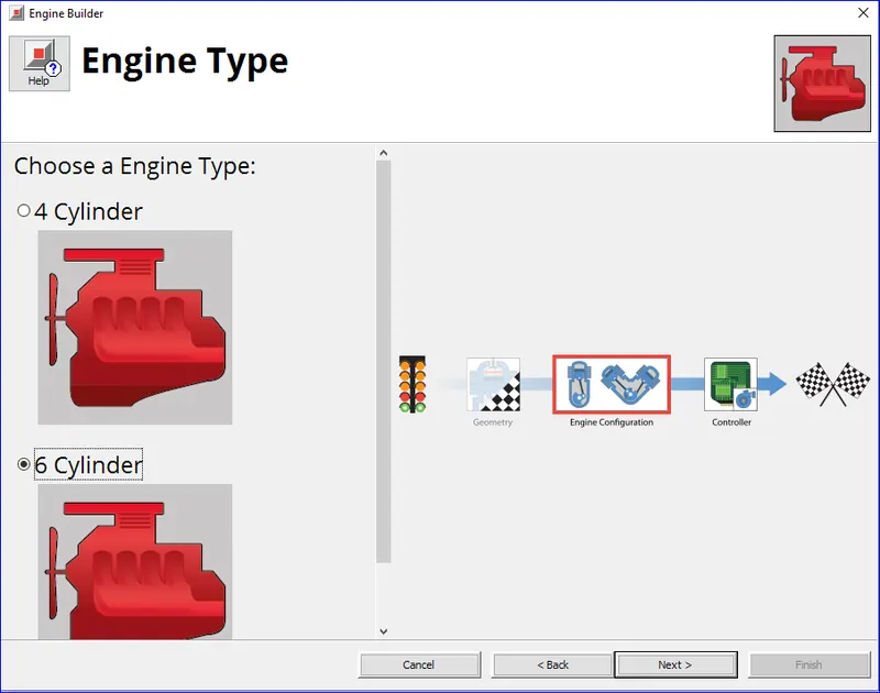
2. Build FRM Model for following configuration using FRM builder approach (50 marks)
- Bore 102 mm stroke 115 mm CR 17
- No of cylinder 6
- CI engine
- Twin Scroll Turbine
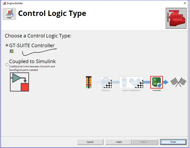
- GT Controller
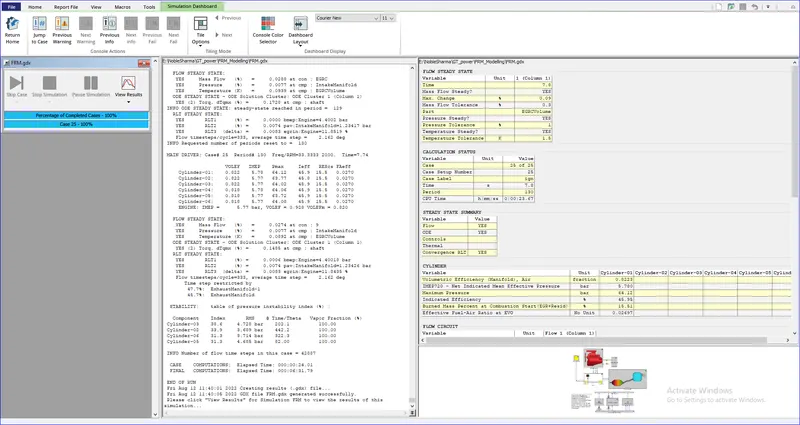
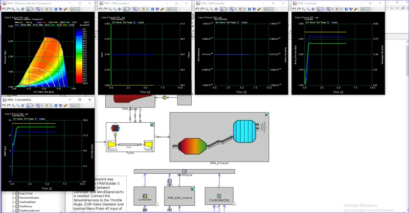
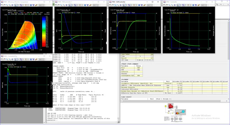
- Run all cases