Week 7 - CHT Analysis on a Graphics card
AIM : To perform the steady-state conjugate heat transfer analysis on the given model of a graphics card.
OBJECTIVES :
- Setting up the Graphic card Geometry in Spaceclaim.
- Create optimal meshing for the model in Ansys Mesher.
- Setup the model for the analysis from the given data.
- Run the simulation for a Preliminary mesh and a Refined mesh
- Run the CHT analysis by varying the velocity from 1m/sec to 5m/sec for at least 3 velocities and discuss the results.
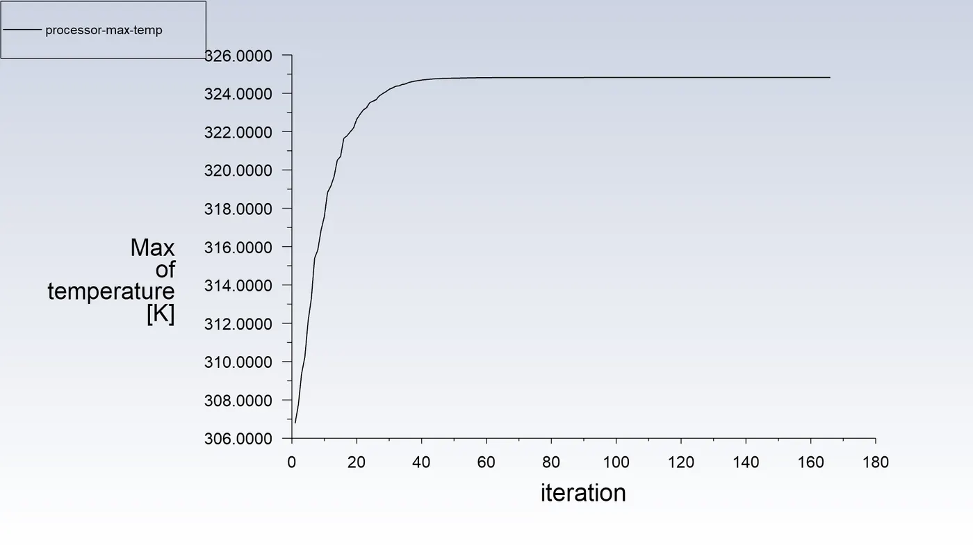
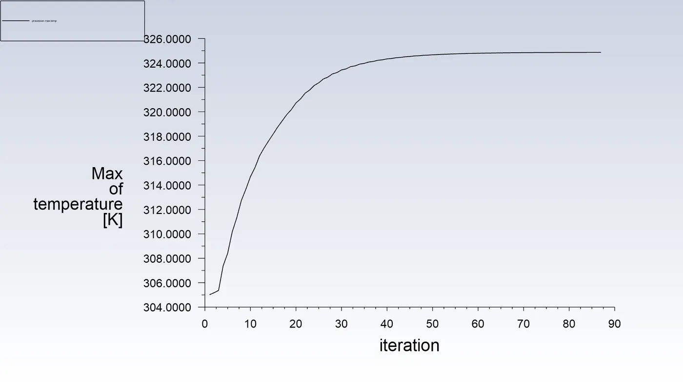
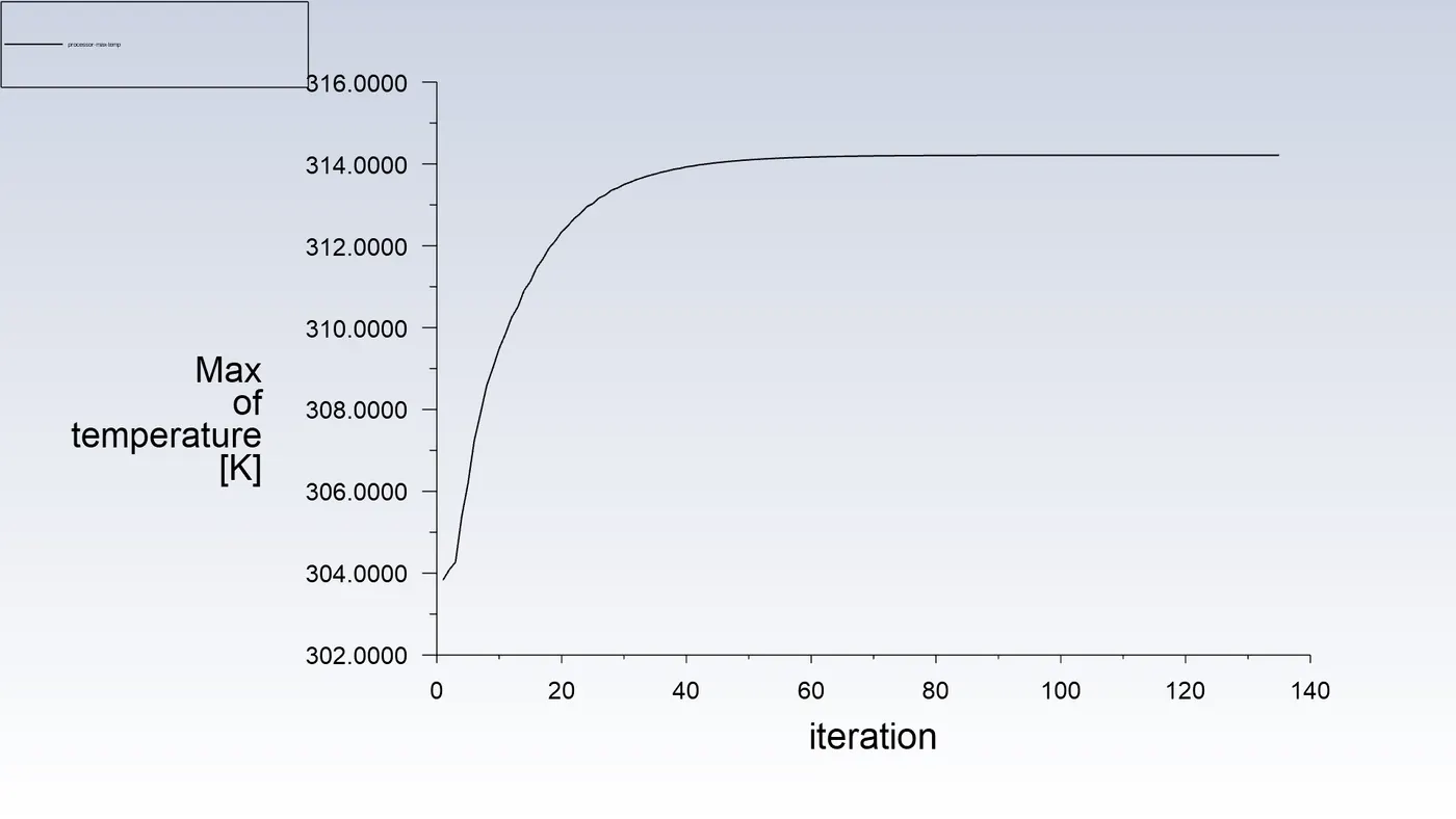
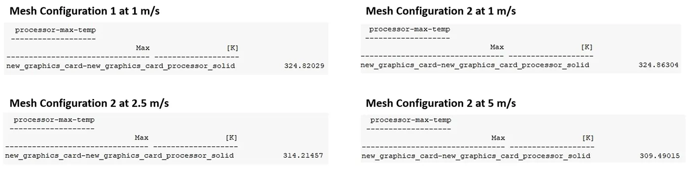
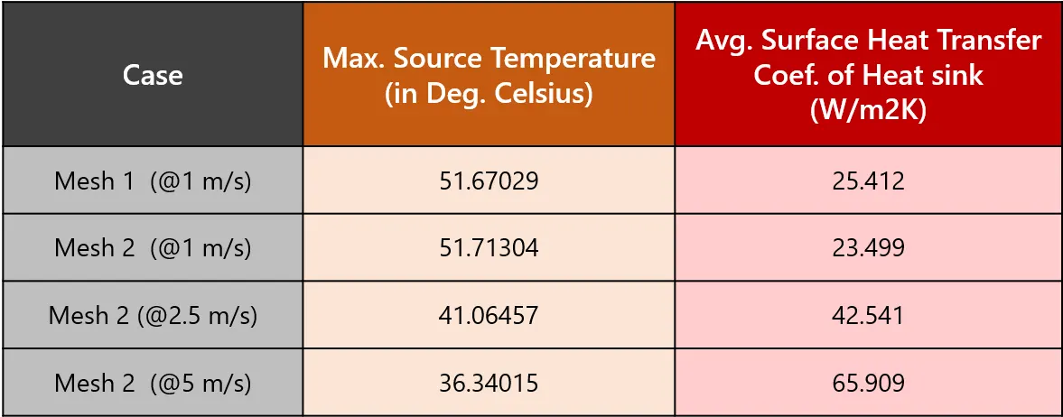
- Find out the maximum temperature and heat transfer coefficient attained by the processor.
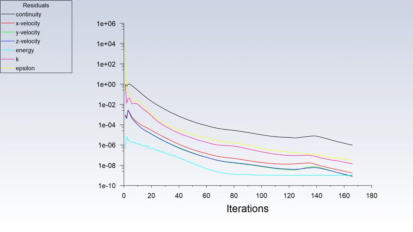
- Prove that the simulation has achieved convergence with appropriate images and plots.
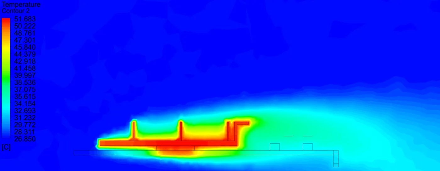
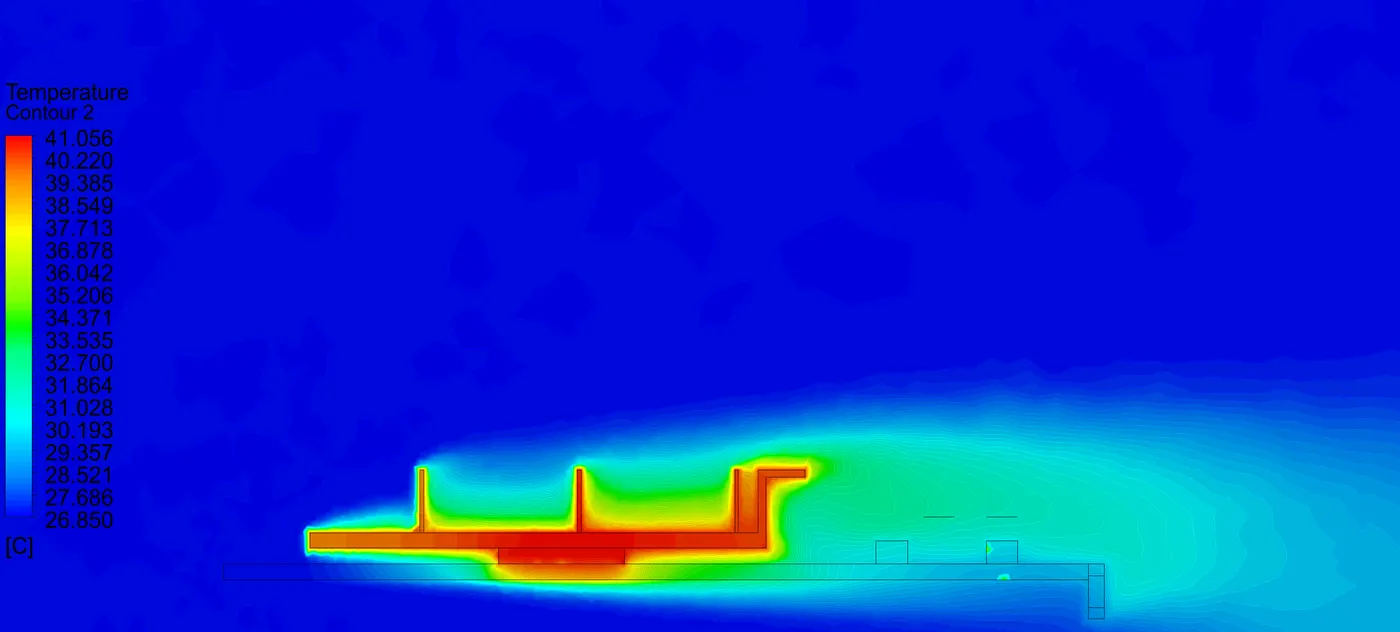
- Identify potential hotspots on the model.
INTRODUCTION :
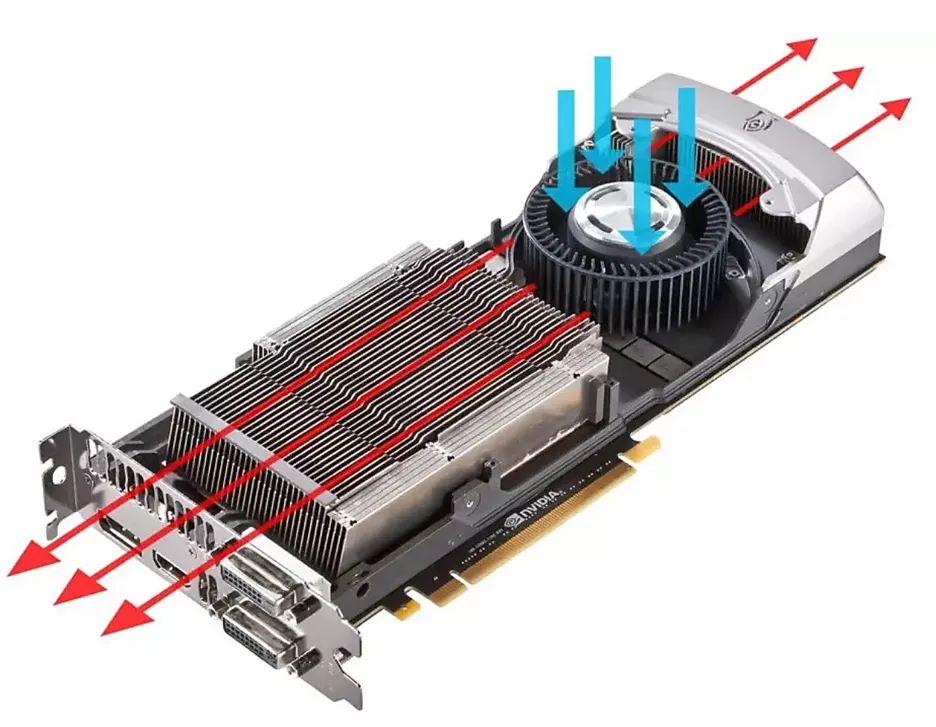
Graphic Card or GPU is an integral part of modern computer devices, which performs the graphical computation for computer UI output. And modern High Power graphic dissipates high amount of heat, so its very important to maintain the cooling of the GPU. As not only the high temperatures can damage/ reduce life of the GPU but also effects the computational performance of the GPU. Better cooling and temperatures enables GPU to perform at much higher frequencies and delivery high GPU performance.
Therefore, CHT analysis has become important part of the GPU industry inorder design an optimum thermal managment system for the Graphic Cards.
STEPS / PROCEDURE :
1) Geometry
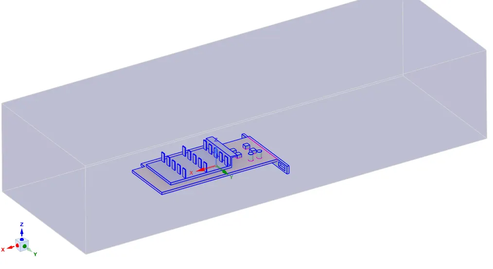
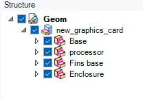
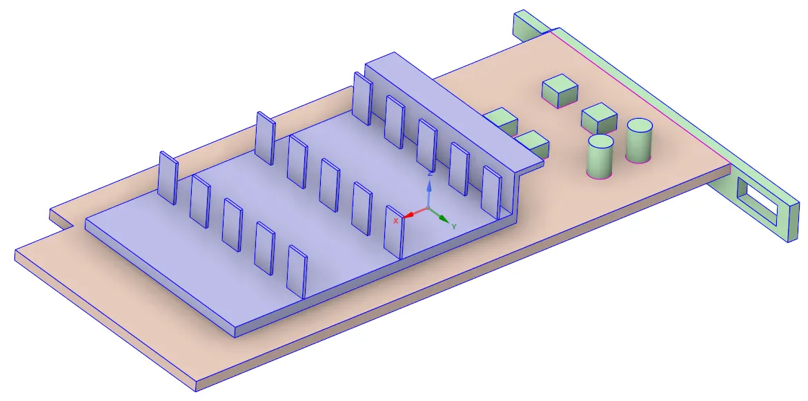
The Following is the geometry based on given data in spaceclaim -
Make sure to enable share topology
2) Meshing
After doing Geometry preparation, we gone open the geometry in Ansys Mesher via workbench -
- Creating Named Selections
- Assigning proper mesh sizing
- Checkng mesh quality.
Following are the 2 Mesh Configurations for the Analysis.
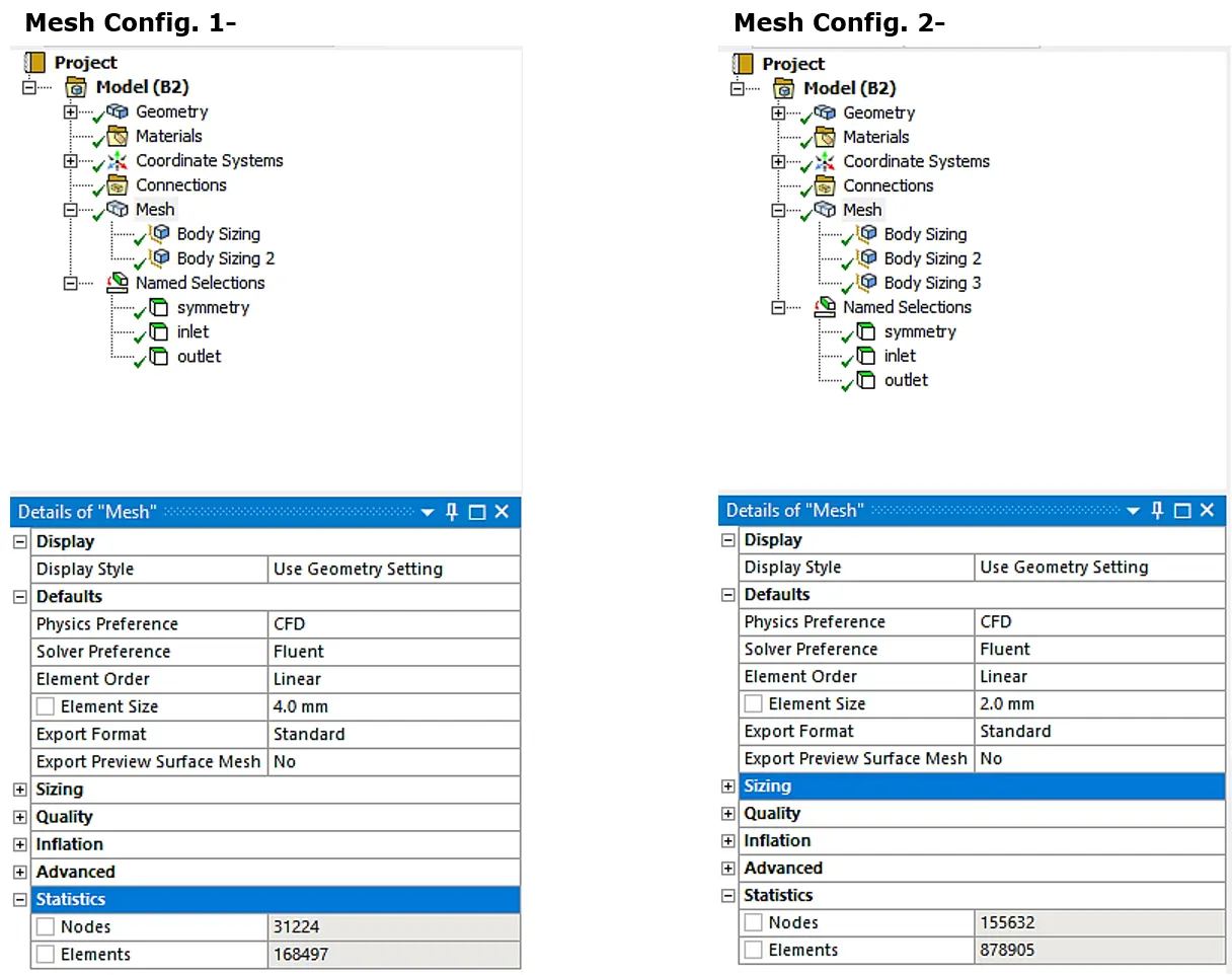
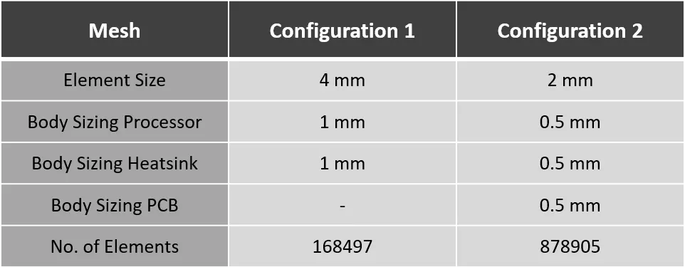
Mesh Quality Verification-
Following is the surface mesh And Element quality of the Case Setup -
i) For Mesh Configuration 1 -
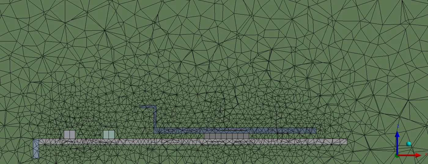
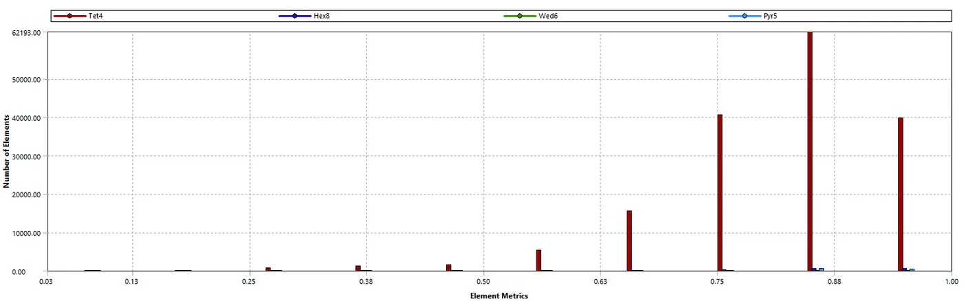
ii) For Mesh Configuration 2 -
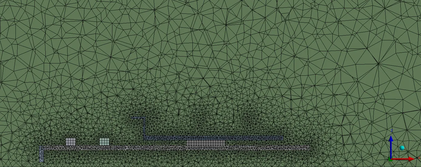
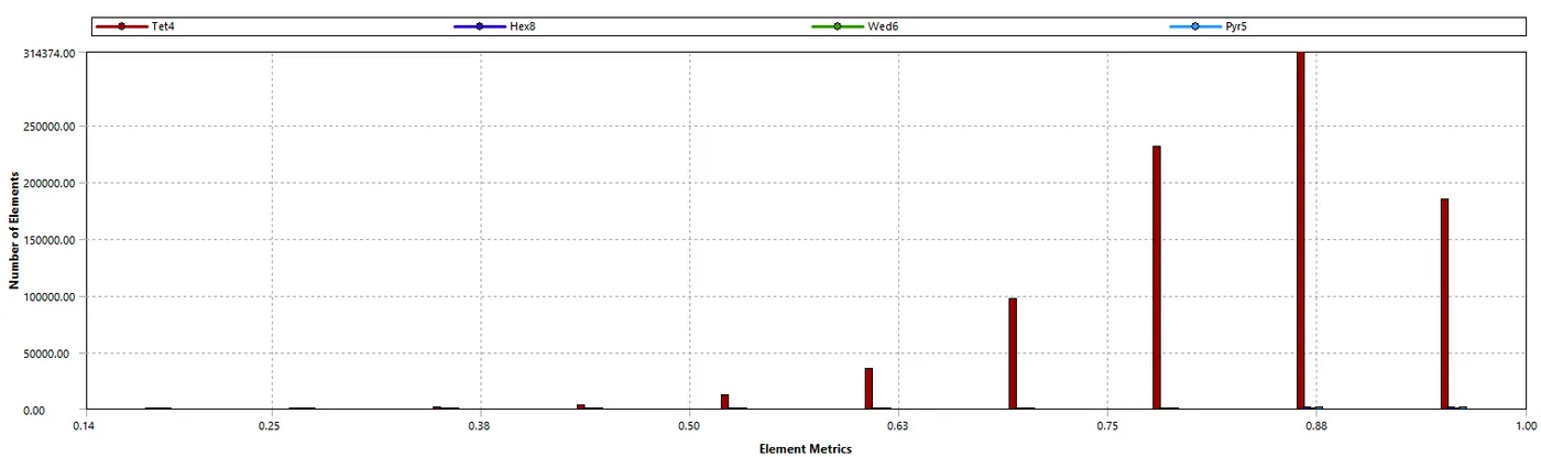
We can the mesh quality is very satisfied. 90% of the mesh cell are lying on good quality range.
3) Solver Settings -
Closing the Mesher & opening the Fluent Solver from the workbench
Checking the the Double precision option and selecting no. of parallel process.
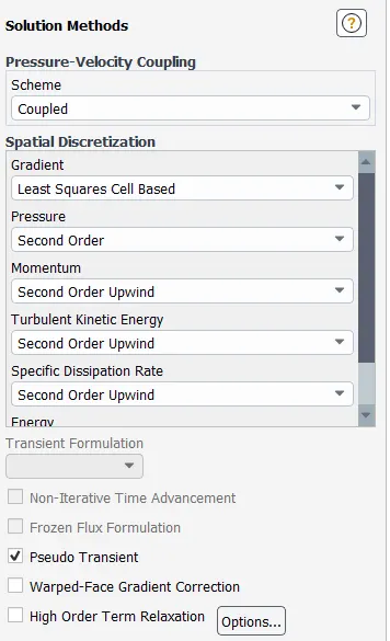
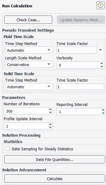
Setting solver settings and initialization values.
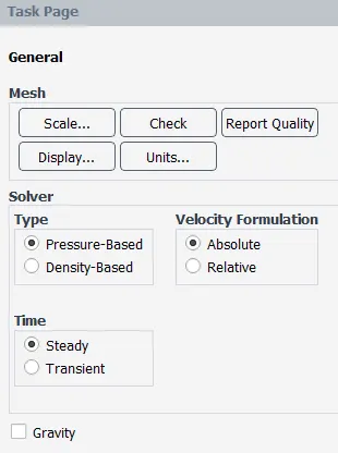
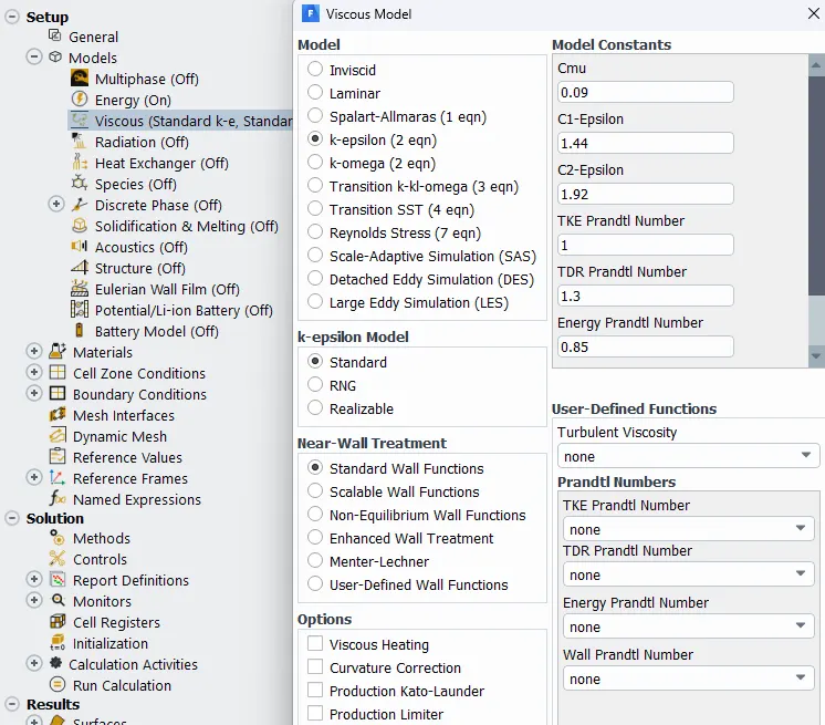
Material Assignment -
Fins - Aluminium
Density = 2719 Kg/m^3
Heat capacity = 871 J/Kgk
Thermal conductivity = 202.4 W/mK
Processor – Silicon
Density = 2000kg/m^3
Heat capacity = 710J/KgK
Thermal Conductivity = 150W/mK
PCB – FR4
Density – 1850 g/m^3
Heat capacity = 950 j/KgK
Thermal conductivity – 0.29 W/mK
Fluid – Air
Density = 1.225 kg/m^3
Heat capacity = 1006.43 j/KgK
Thermal Conductivity = 0.0242 W/mK
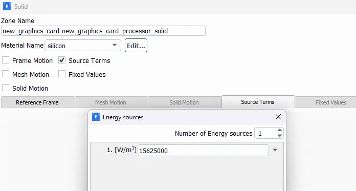
Setting Source properties for the Heat Dissipation -
Taking the Heat dissipation from the processor of 10 Watts.
For the Processor dimensions 8mmx8mmx1mm
Calculating Power Density -
100/(0.08*0.08*0.001) = 15625000 W/m^3
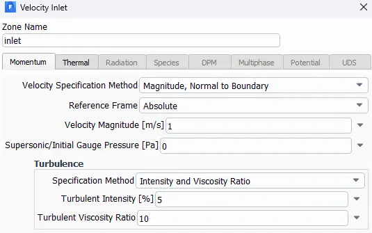
Setting Inilization, here we are using Hybrid Initialization.
POST PROCESSING :
Outputs
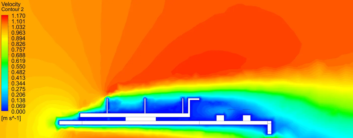
1. For Mesh Config. 1 -
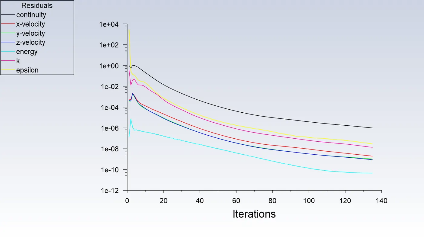
Residuals and Solution Plot -
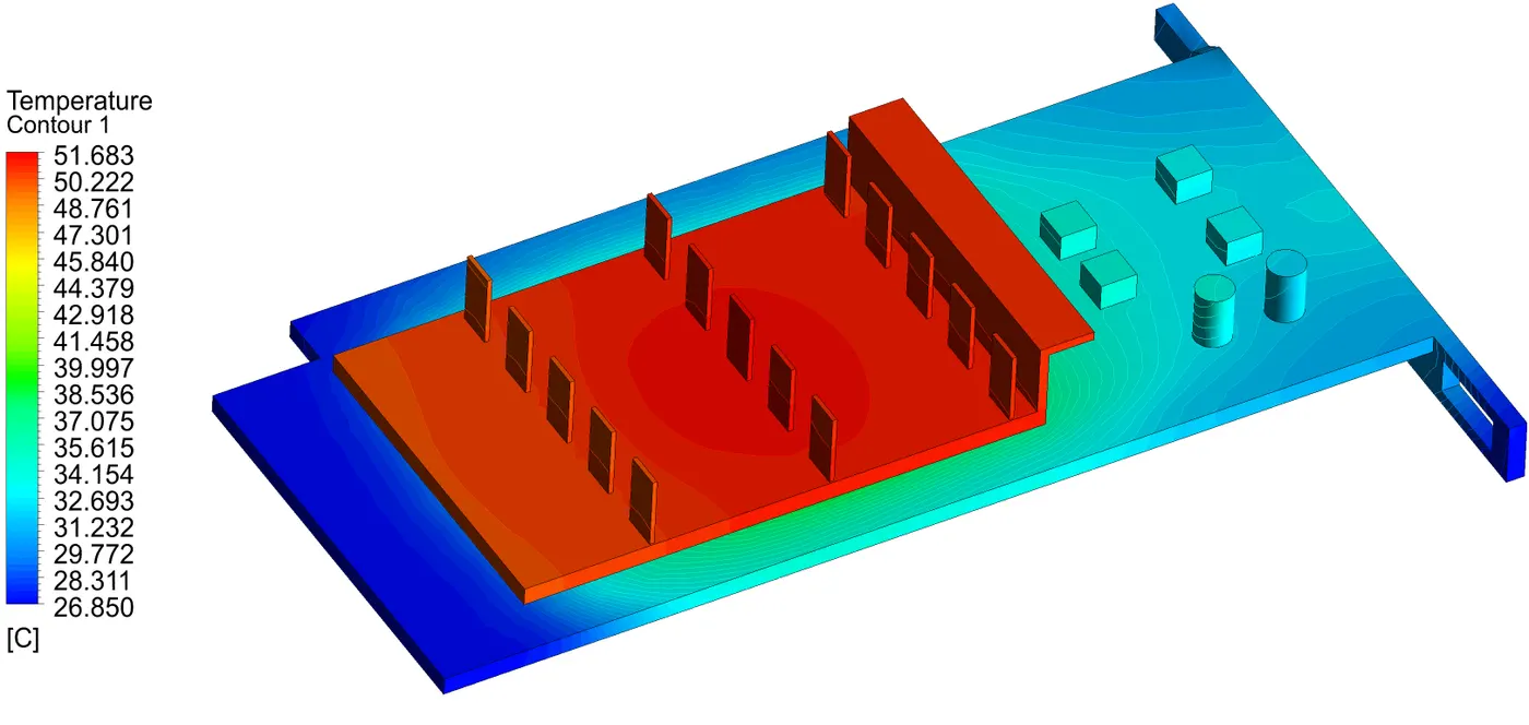
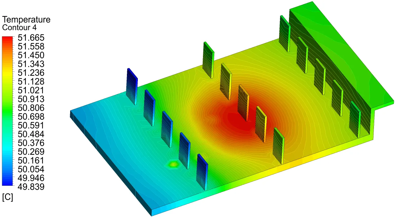
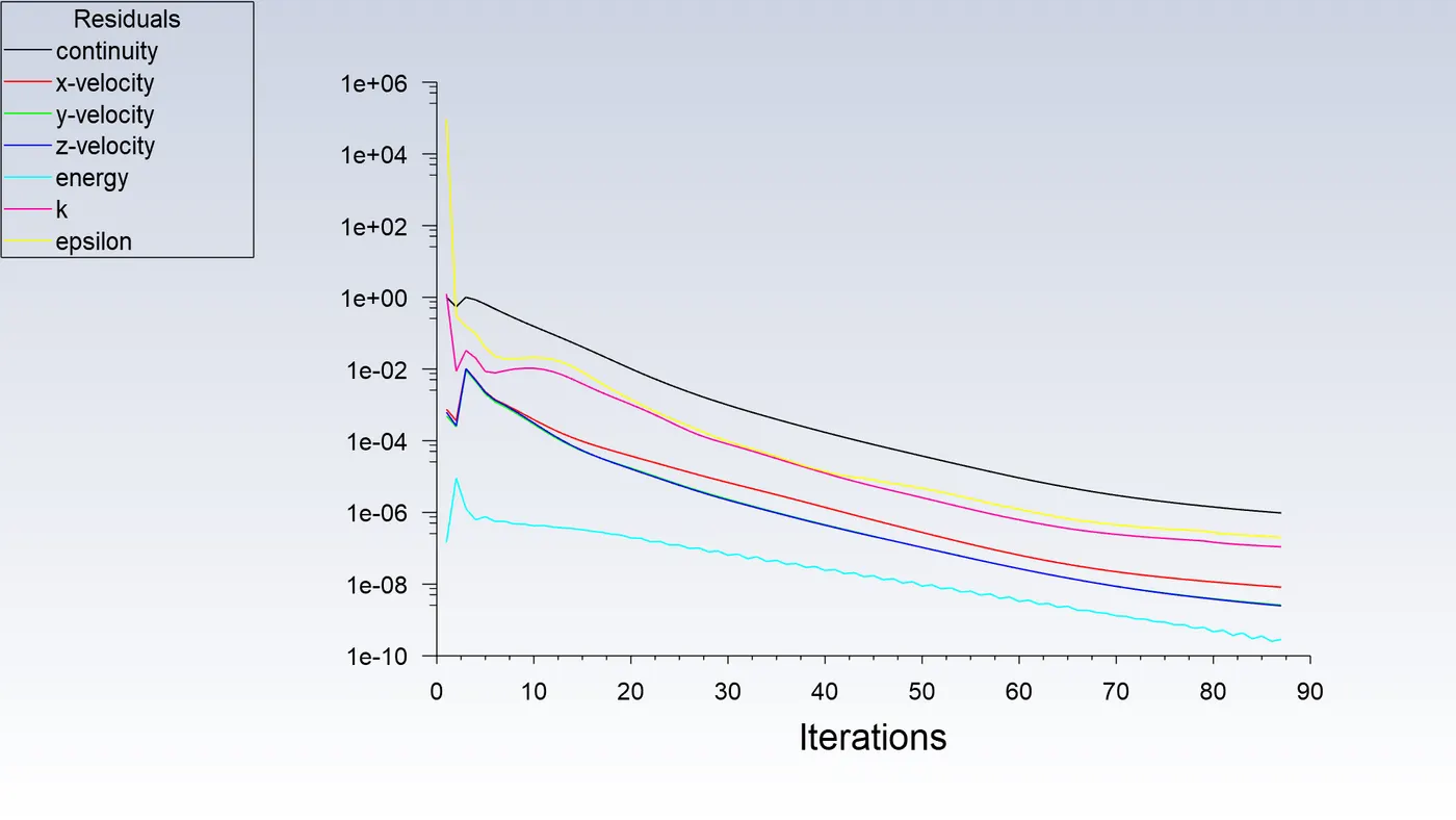
2. For Mesh Config. 2 at 1 m/s-
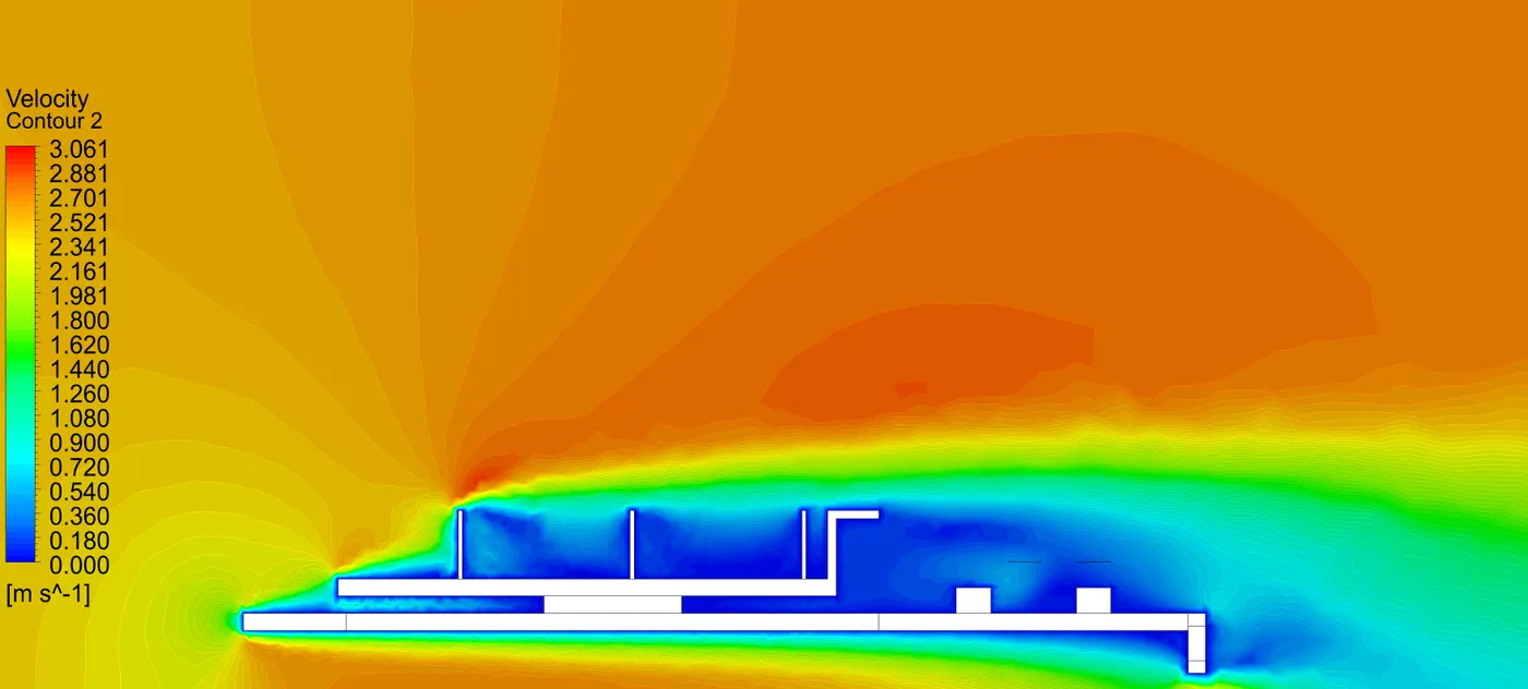
Residuals and Solution Plot -
2. For Mesh Config. 2 at 2.5 m/s-
Residuals and Solution Plot -
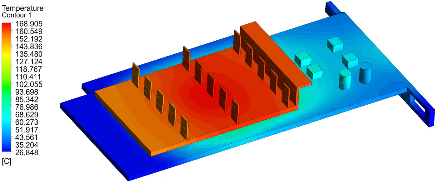
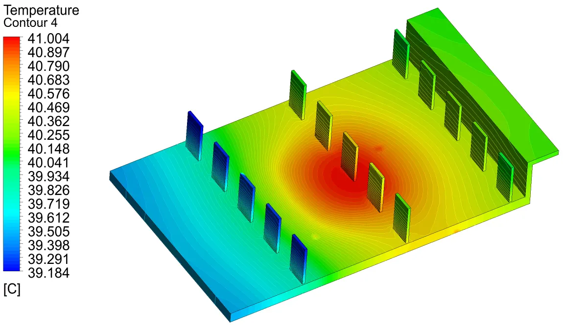
4. For Mesh Config. 2 at 5 m/s -
Residuals and Solution Plot -
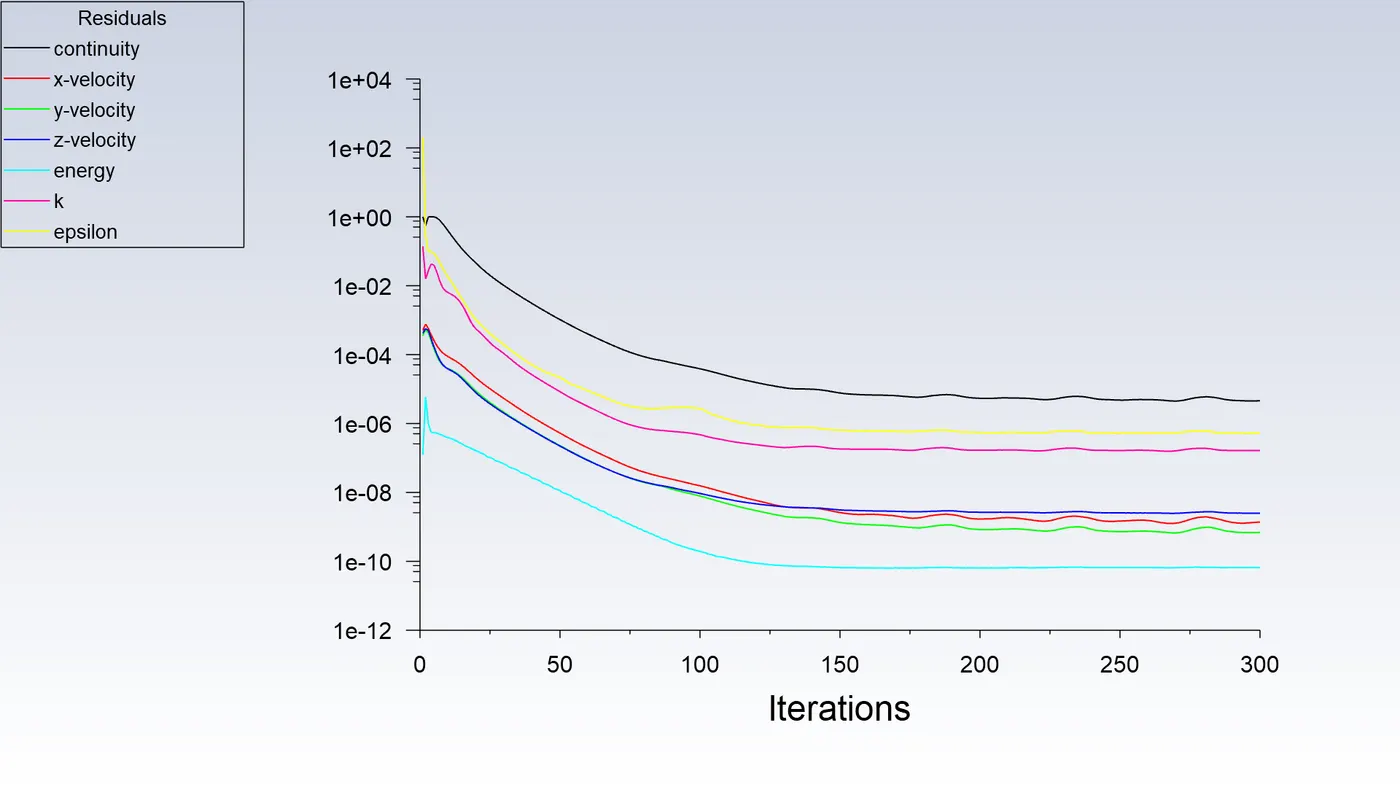
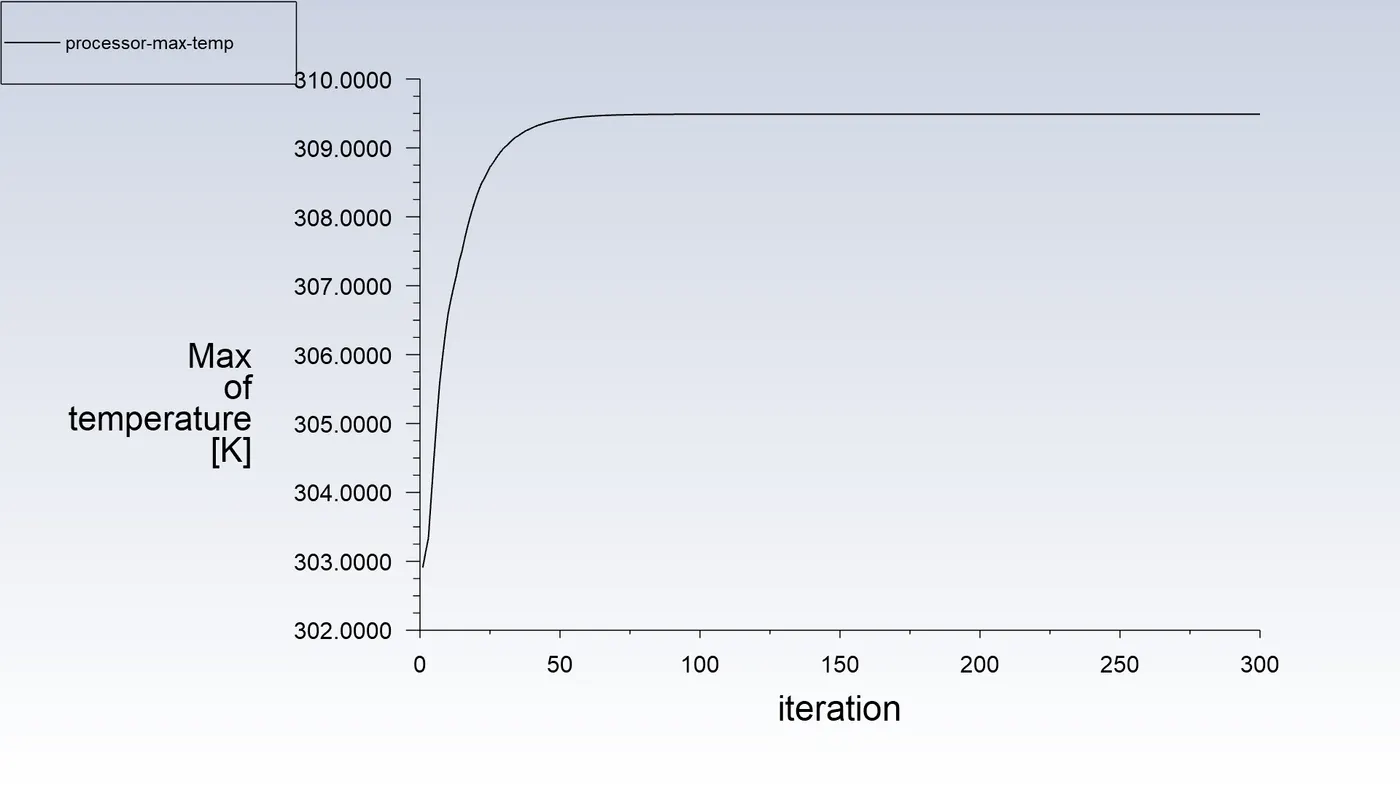
RESULTS :
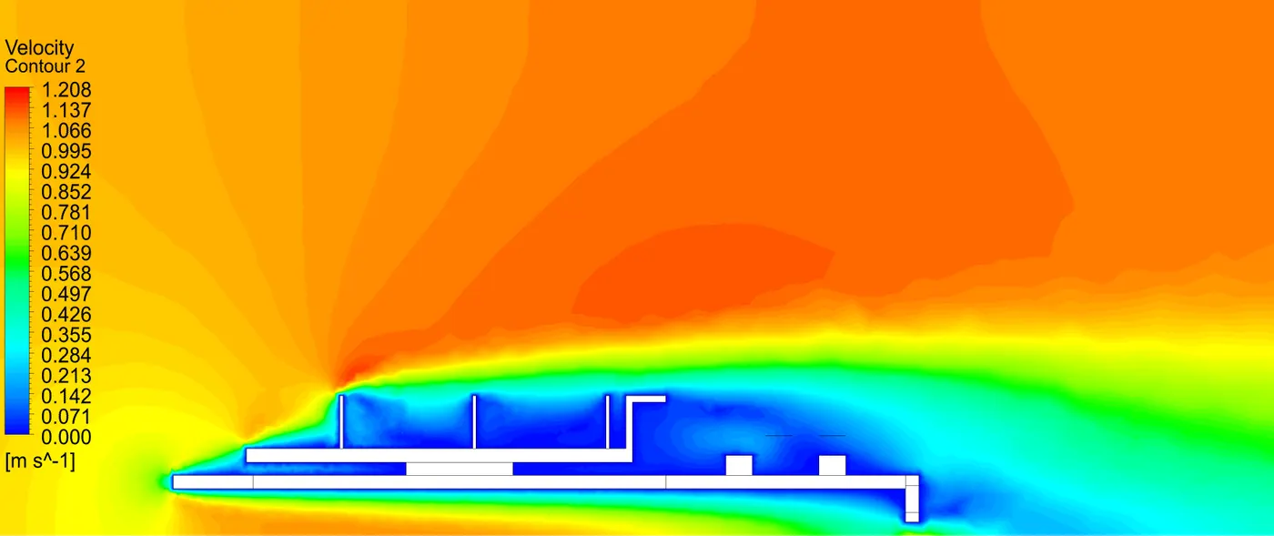
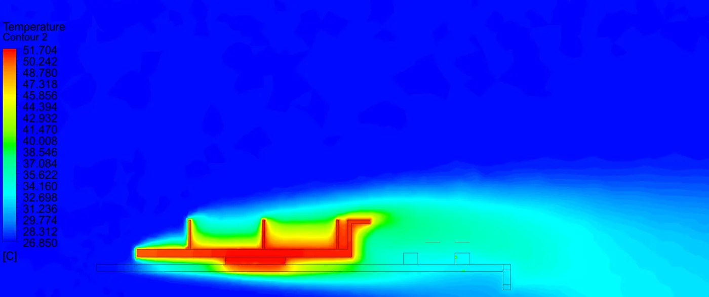
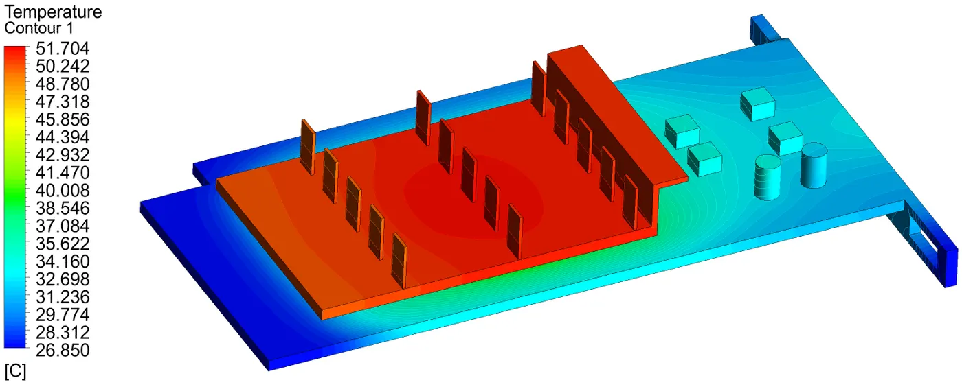
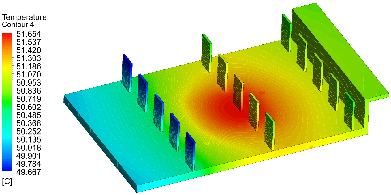
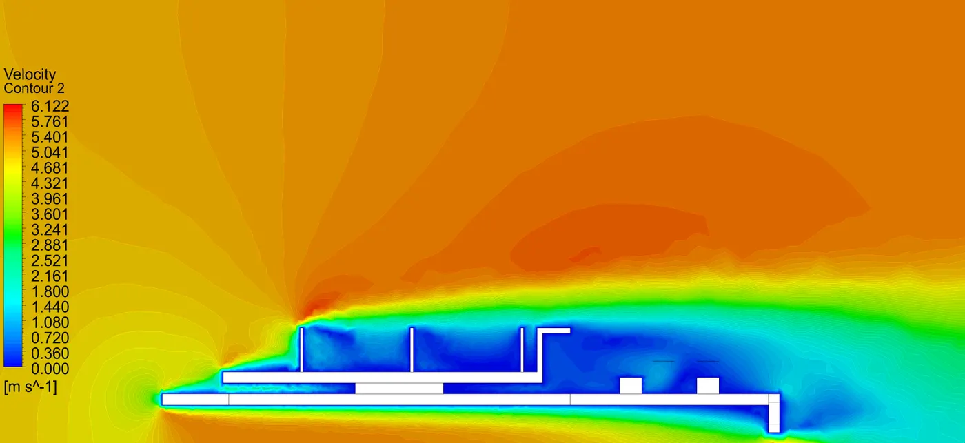
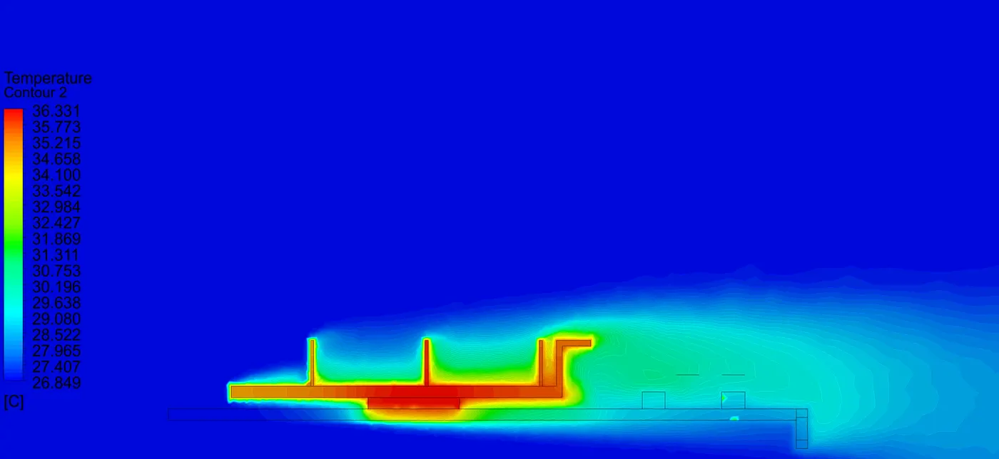
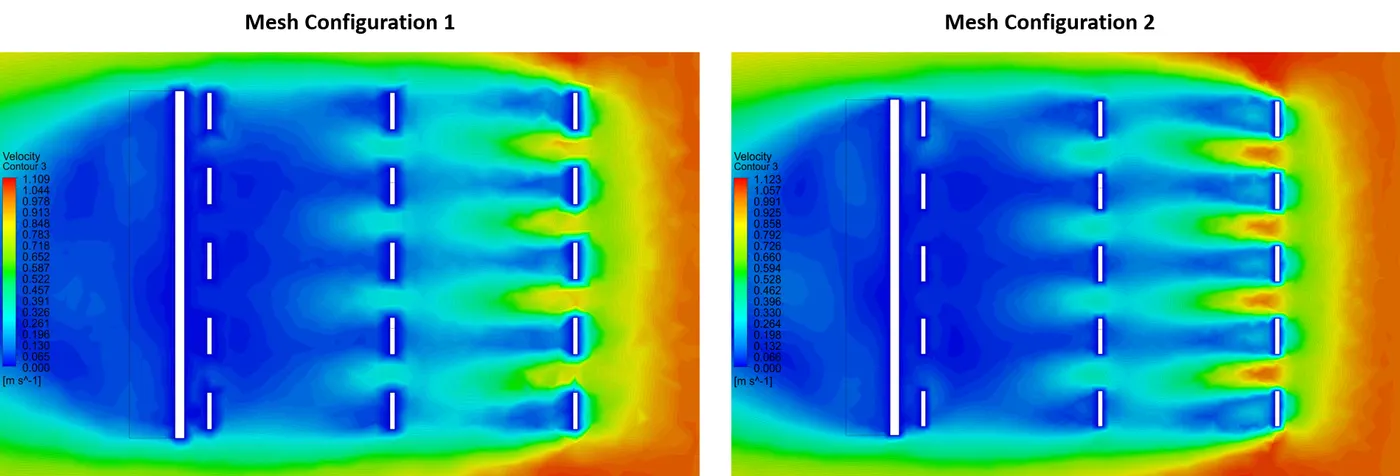
The Following are the results visualization comparing the two mesh configurations -

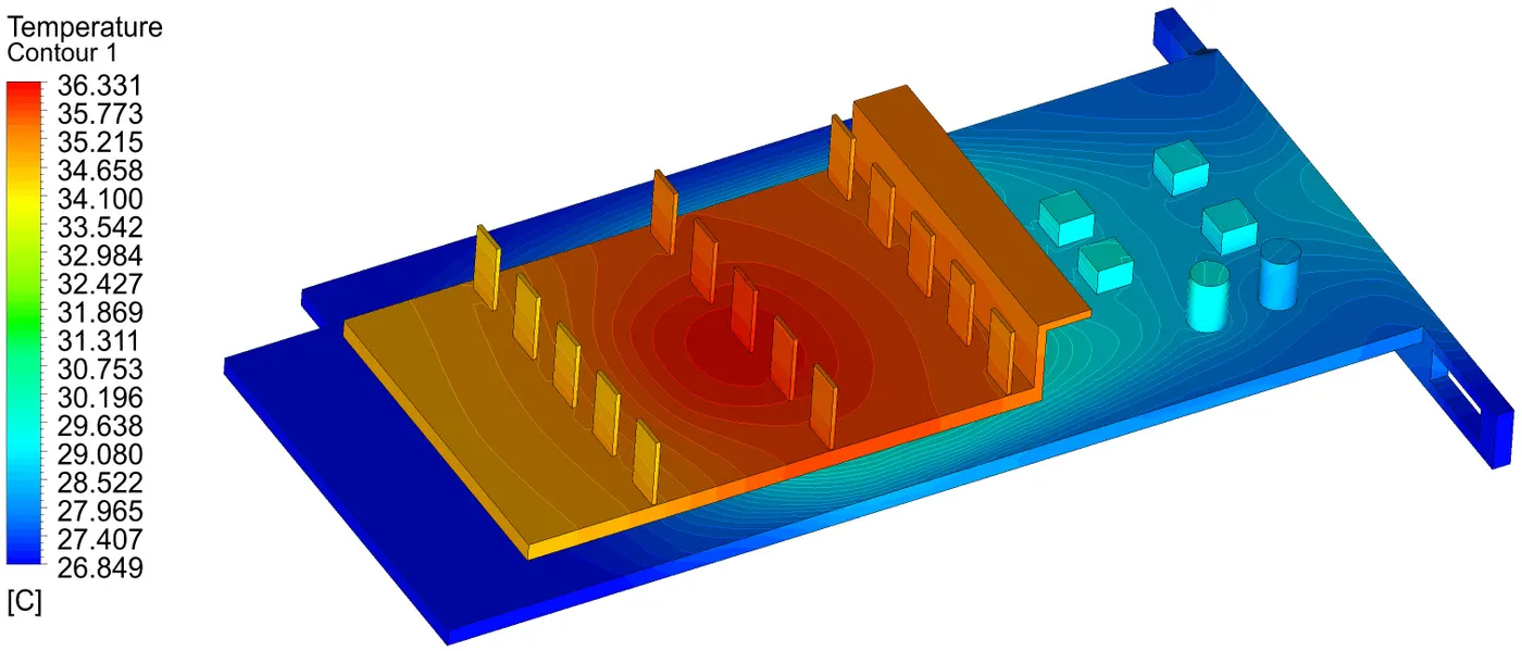
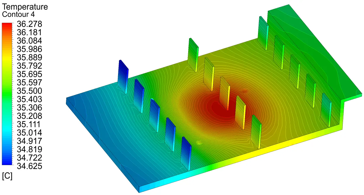
Following are the Results for all the cases -
CONCLUSION :
We have successfully performed the CHT analysis of the Graphic card in Ansys fluent.
The solver was set up using suitable settings to incorporate the physical phenomena.
We were able to generate required contours for analyzing.
The following conclusions can be drawn based on the simulation results after running -
- All the simulations reached convergence; having residuals less than `10^-5`.
- We observe that finer mesh gives more accurate results, also gives more accurate and informative contours to analyse.
- From the results we can see that, as increase the speed of convective air the temperature decreases.
- From the contours we can observe that hotspot are just below the source where it is attached PCB.
The accuracy of the simulation can increased by more mesh refinement near the fins and the conduction path from the source to heat sink.
REFERENCE :
- Conjugate Heat Transfer - https://www.comsol.com/blogs/conjugate-heat-transfer/
- Advanced Cooling for Power Electronics - https://www.electronics-cooling.com/2017/07/advanced-cooling-power-electronics/
- How to Select a Heat Sink - https://www.electronics-cooling.com/1995/06/how-to-select-a-heat-sink/