Week 7 - CHT Analysis on a Graphics card
STEADY-STATE CONJUGATE HEAT TRANSFER ANALYSIS ON A GRAPHICS CARD
AIM : To Simulate Conjugate Heat Transfer (CHT) Analysis on a model of a graphics card.
Objectives:
- Run the simulation by varying the velocity from 1m/sec to 5m/sec for at least 3 velocities and discuss the results.
- Find out the maximum temperature and heat transfer coefficient attained by the processor.
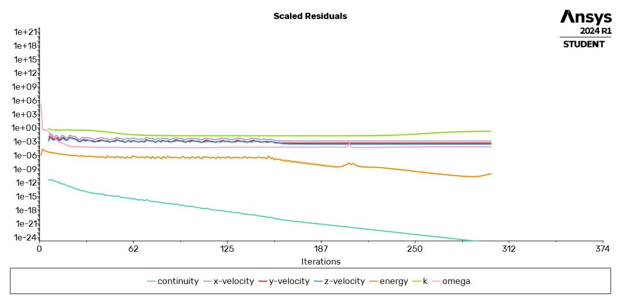
- Prove that the simulation has achieved convergence with appropriate images and plots.
- Identify potential hotspots on the model.
THEORY :
- Conjugate Heat Transfer (CHT) is a type of analysis used in Computational Fluid Dynamics (CFD) to simulate the heat transfer between fluid and solid domains. This technique is particularly useful in situations where heat transfer is affected by the interaction between the fluid and the solid, such as in heat exchangers, cooling of electronic components, and thermal management in engines.
- In a CHT analysis, the heat transfer processes in both the solid and fluid domains are solved simultaneously. This allows for a more accurate prediction of temperature distribution and heat flux, as it takes into account the effects of conduction in the solid, convection in the fluid, and heat transfer at the fluid-solid interface.
- Conduction: This is the heat transfer within the solid domains. It occurs due to the temperature gradient within the solid.
- Convection: This is the heat transfer within the fluid domains and at the solid-fluid interfaces. It can be due to forced convection (caused by external forces like a fan or pump) or natural convection (caused by density differences within the fluid due to temperature variations).
- The main steps in a CHT analysis are:
- Mesh Generation: The fluid and solid domains are discretized into small elements.
- Boundary Condition Specification: The thermal and flow conditions at the boundaries of the domains are defined.
- Solver Settings: The equations for momentum, energy, and mass conservation are set up for the fluid and solid domains.
- Solution Iteration: The solver iterates until a converged solution is found.
- Post-processing: The results are visualized and analyzed.
- By providing a detailed understanding of heat transfer processes, CHT analysis can help in optimizing the design and performance of thermal systems. However, it’s important to note that CHT analysis can be computationally intensive due to the complexity of the physics involved. Therefore, it’s often used in combination with other simplifying assumptions or modeling techniques to balance accuracy and computational efficiency.
GEOMETRY :
- Import the model into space claim,and change the units.
- enable the enclosure and share topology to avoid the errors while meshing and post processoing.
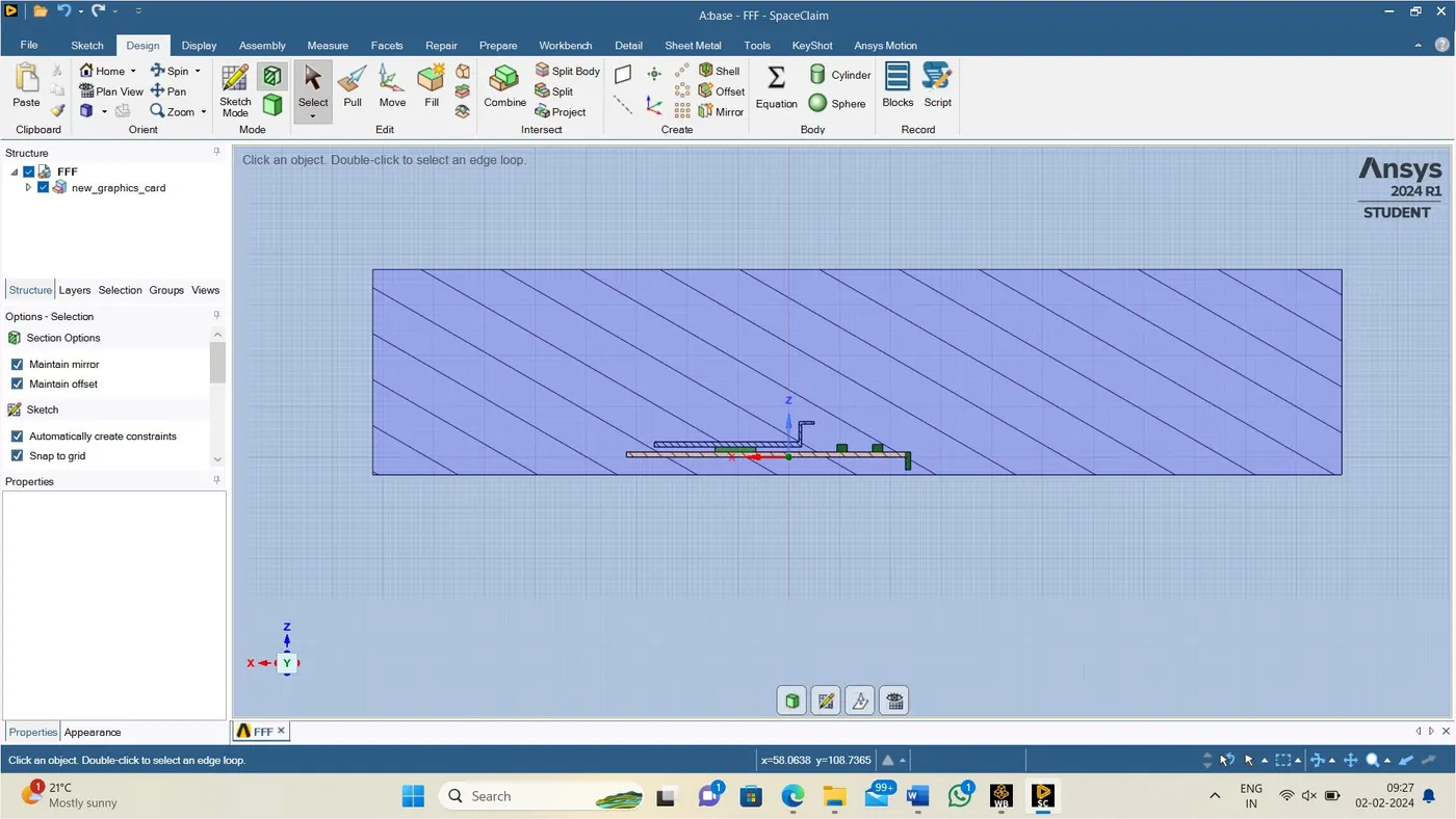
MESH : Meshing is the process of discretization of the simulation domain. That means we split up a large domain into multiple smaller domains and solve equations for them .a multi region mesh is required for a CHT simulation to have a clear definition of the interfaces in the computational domain.
- After update the geometry give name selection according to model.
- After name selection ,generate the base mesh to the model.
- After the base mesh generation insert body size mesh to get better mesh refinement up to maximum limit.
BASE MESH :
Enclosure : 10.289 mm
Fin : default
processor : default
board : defalut

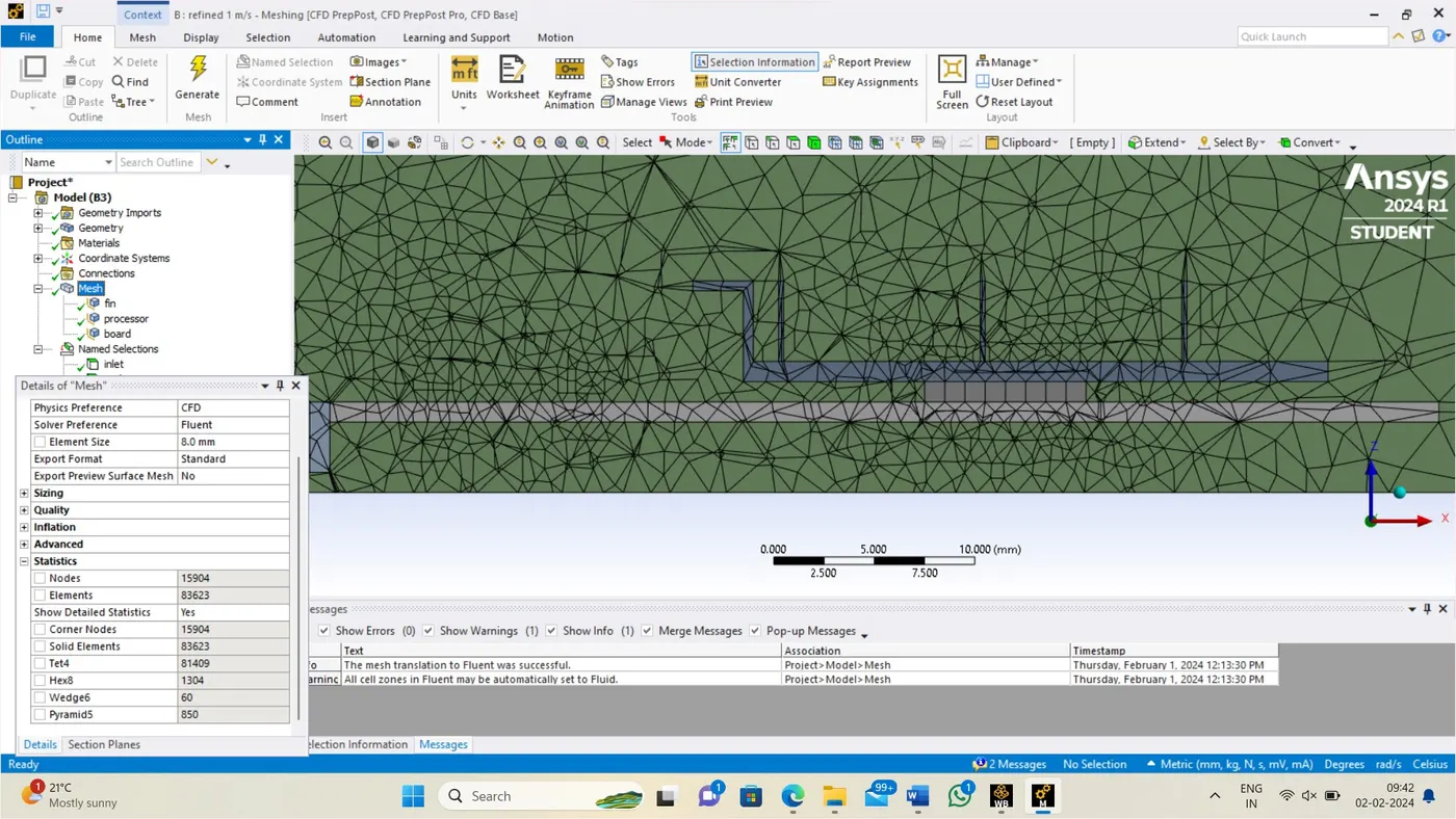
REFINED 1 m/s MESH :
Enclosure : 8 mm
Fin : 5 mm
processor :1 mm
board : 6 mm
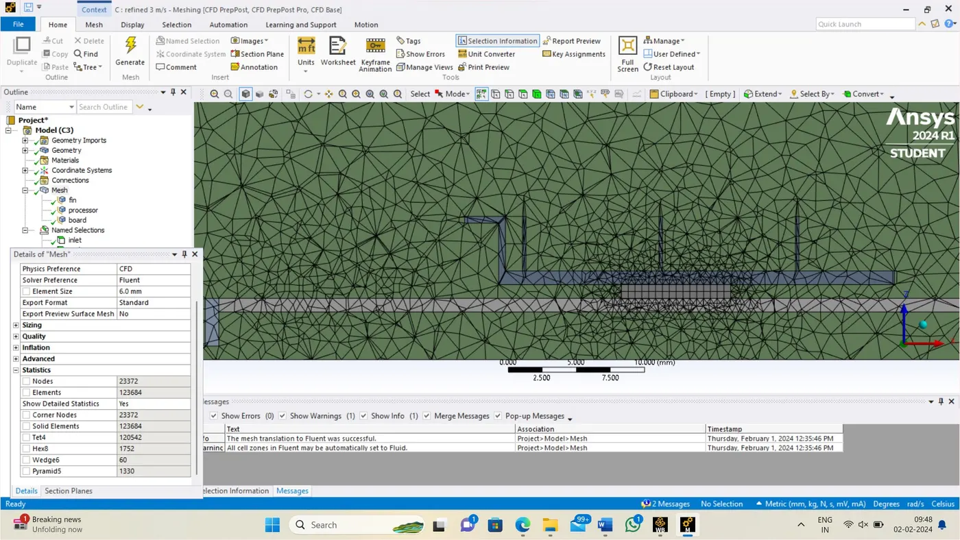
REFINED 3m/s MESH :
Enclosure : 6 mm
Fin : 2 mm
processor :0.5 mm
board : 3 mm
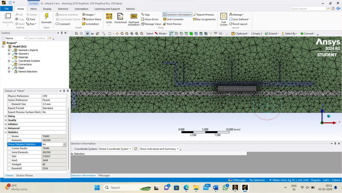
REFINED 5m/s MESH :
Enclosure : 3 mm
Fin : 0.8 mm
processor :0.3 mm
board : 0.9 mm
Fluent setup:
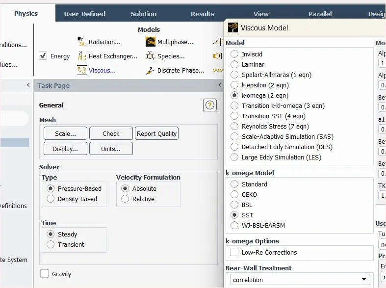
After Updating The Mesh Open Fluent Setup, Select A Pressure-Based Solver Using The Steady-State Time Simulation And Absolute Velocity Formulation Under The General Settings.
Under The Physic Choose The Energy Option As We Are Dealing With Temperature Properties.
Input The Boundary Values, 0 M/S As Inlet Velocity At 300K. Set The Outer Wall Convection Boundary To Convection Type And Input Constant Value Of Heat Transfer Coefficient.
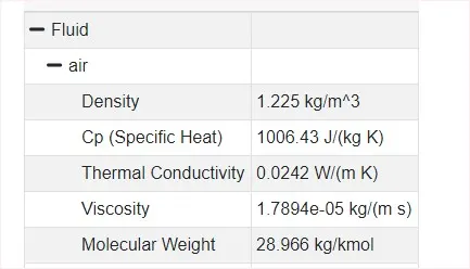
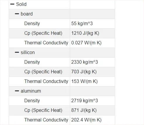
Under Materials, Choose Air As The Fluid material And Aluminium As Solid Material.
Enter The Reference Value As Per The Geometry And Inlet Boundary Conditions.
Initialize The Hybrid Initialization And The Simulation For 300 Iterations.
enable the energy equations.
setting up the physics
SETTING UP THE MATERIALS :
select the physics ,click on materials ,select the fluids or soilds and apply and then close the tab
materials &VALUES :
RESULTS COMPARISION BETWEEN BASE MESH AND REFINED MESH :
BASE MESH :
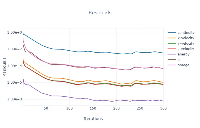
RESIDUAL :
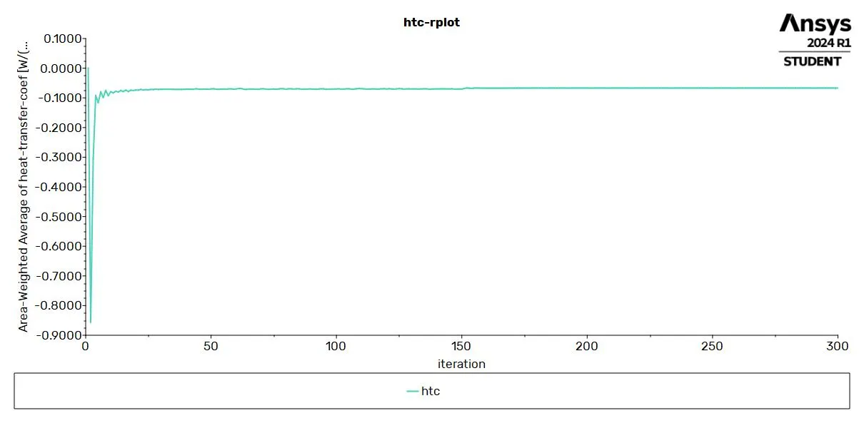
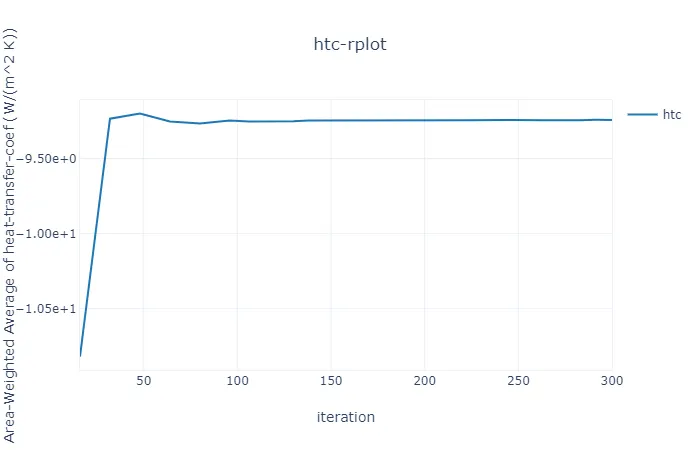
HTC REPORT :
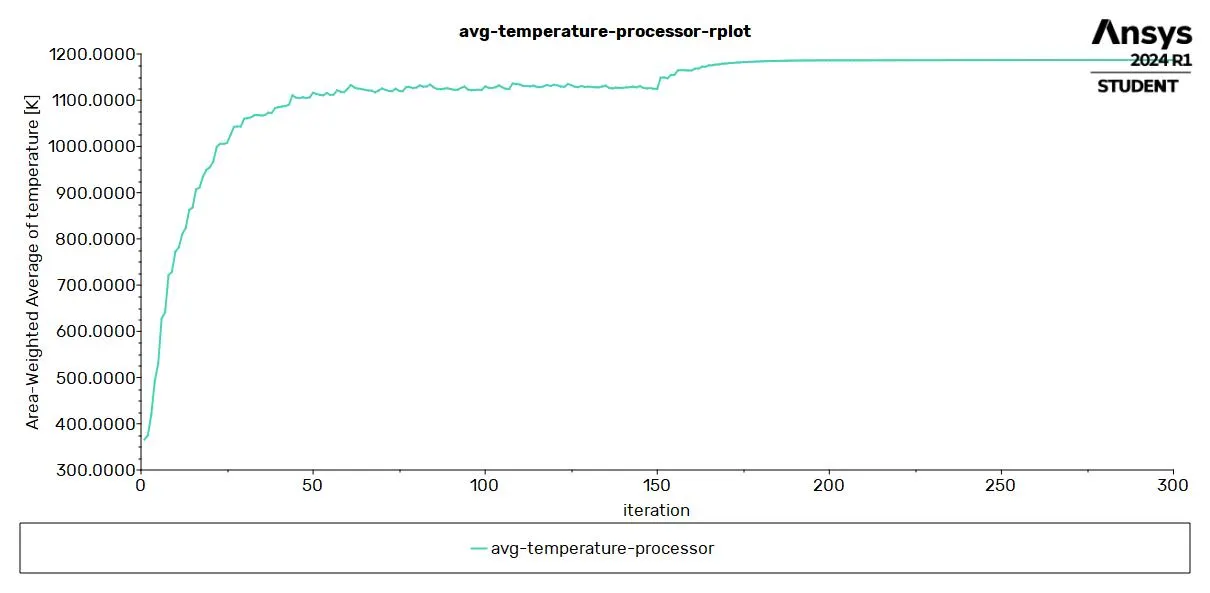
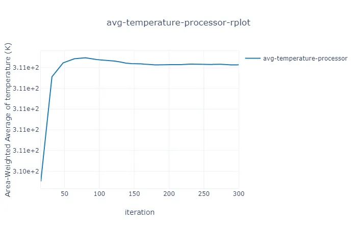
AVG-TEMPERATURE :
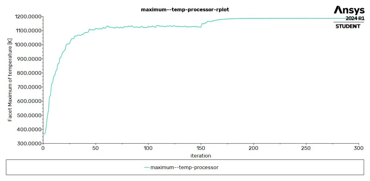
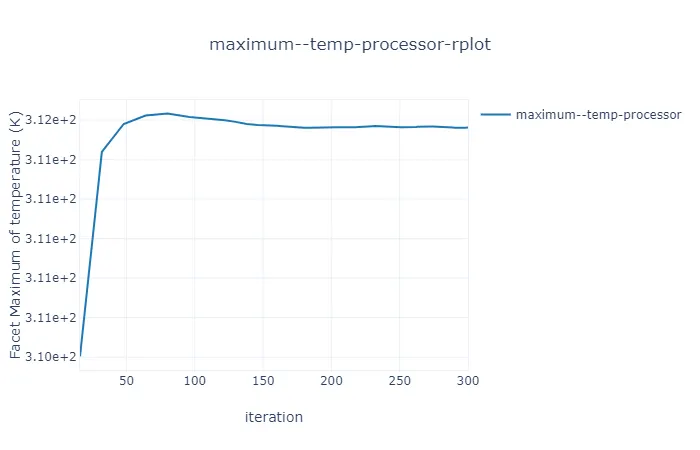
MAX-TEMPERATURE :
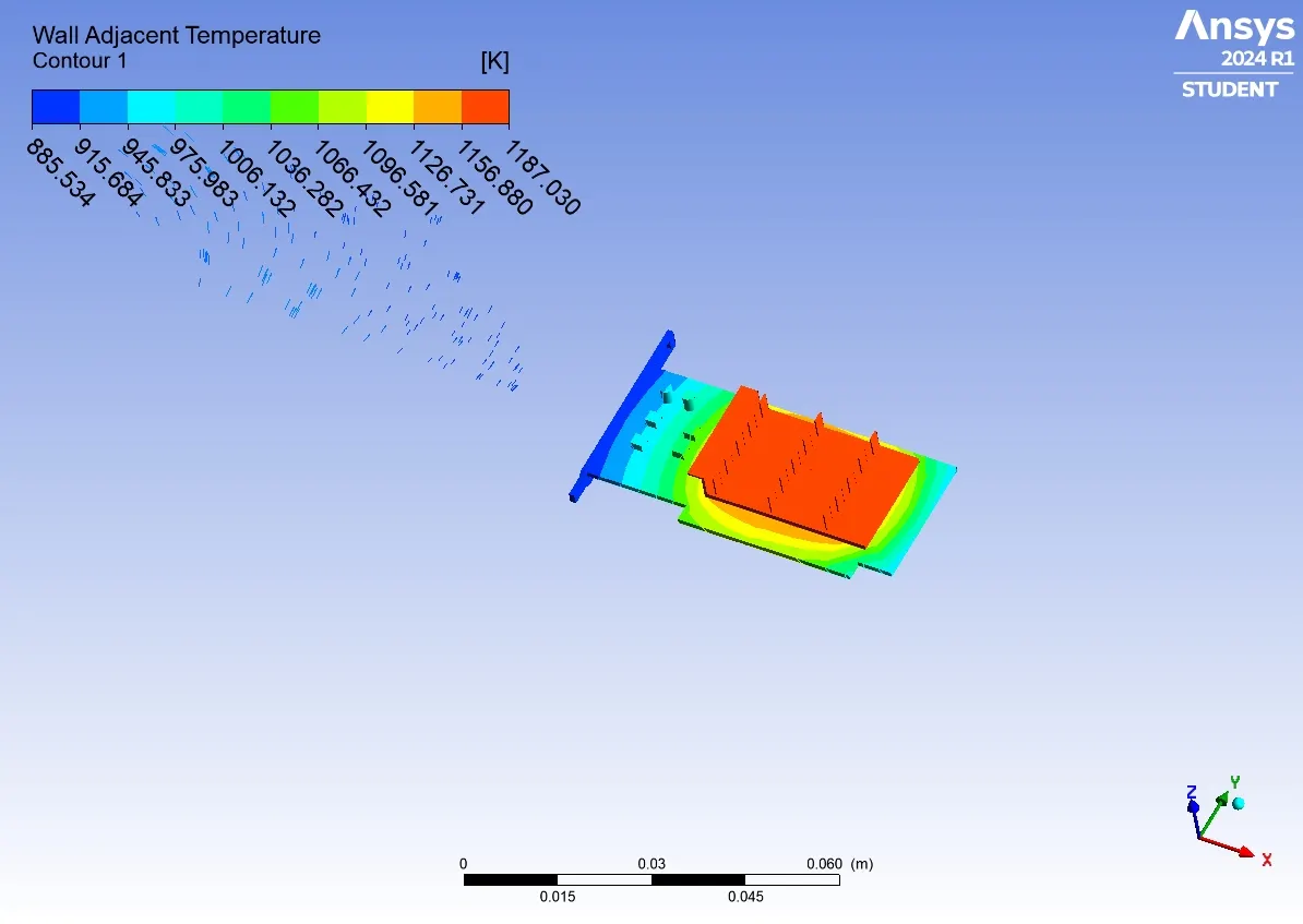
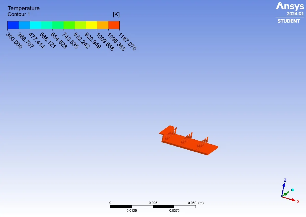
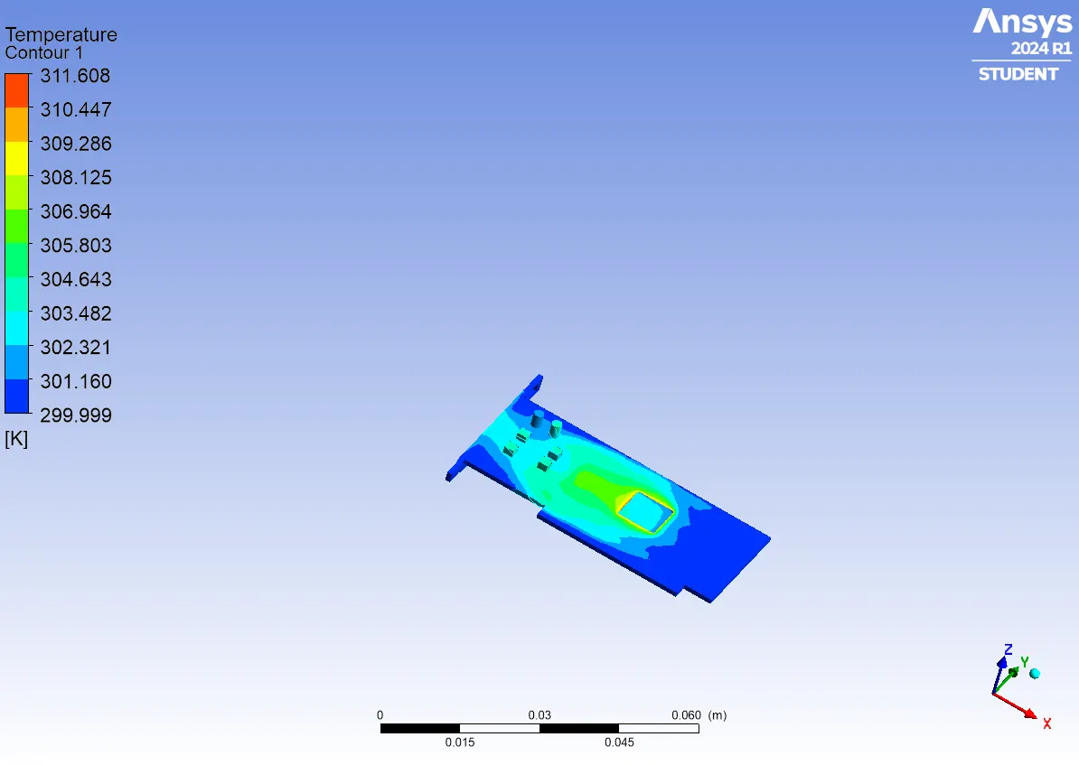
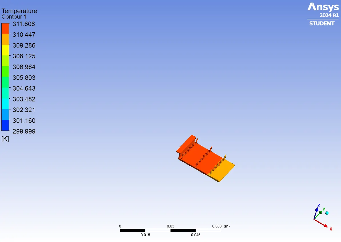
CONTOURS :
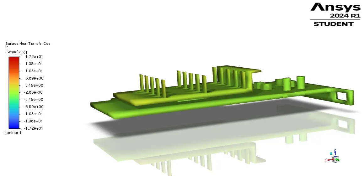
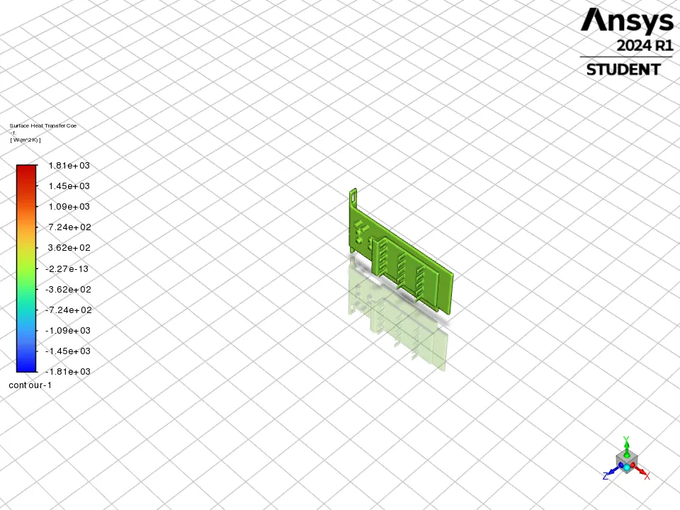
SURFACE-HEAT-TRANSFER-COEFFICIENT :
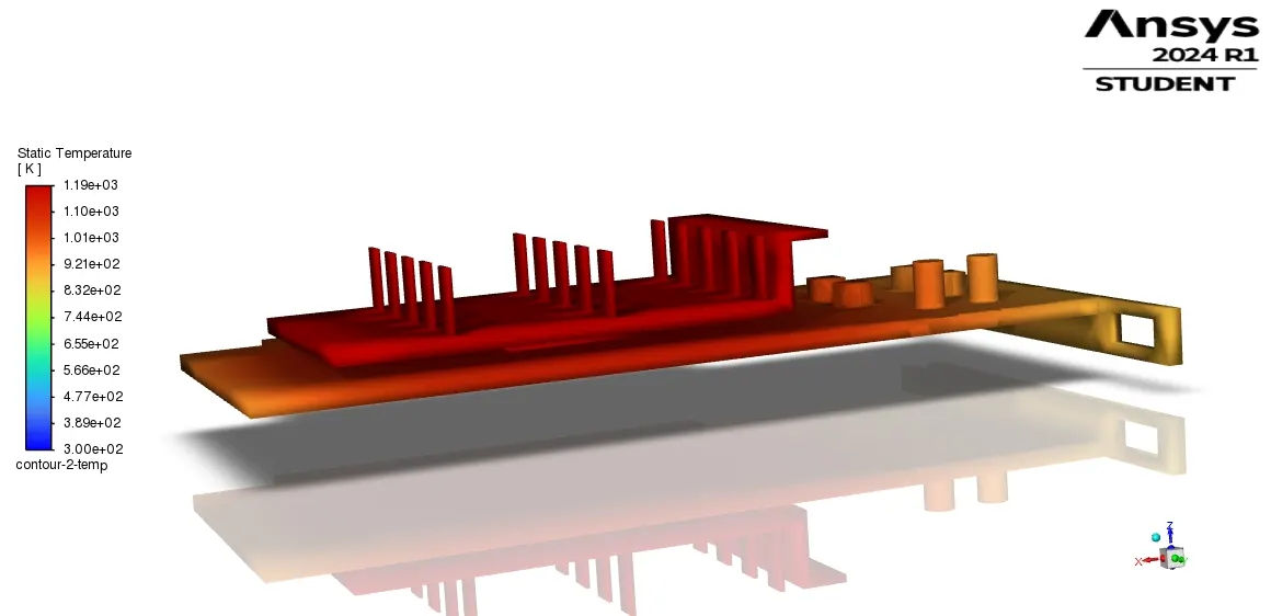
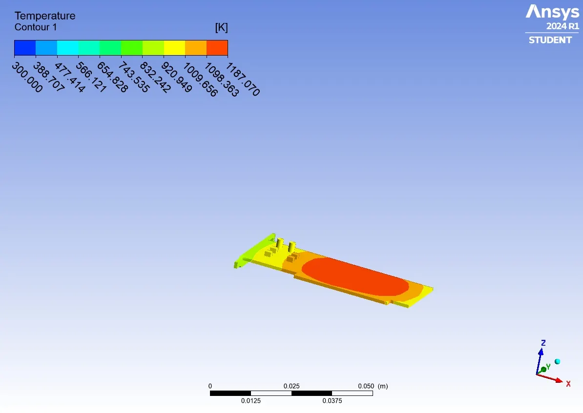
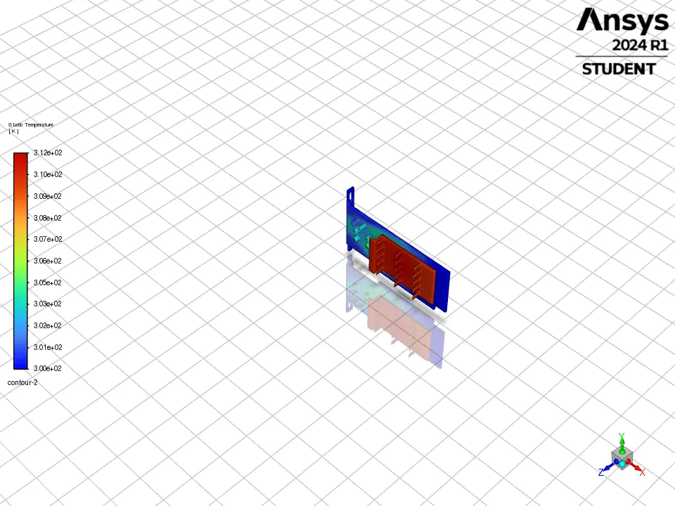
STATIC-TEMPERATURE :
PLOTS :
REFINED MESH :
RESIDUAL :
HTC REPORT :
AVG-TEMPERATURE :
MAX-TEMPERATURE :
CONTOURS :
SURFACE-HEAT-TRANSFER-COEFFICIENT :
STATIC-TEMPERATURE :
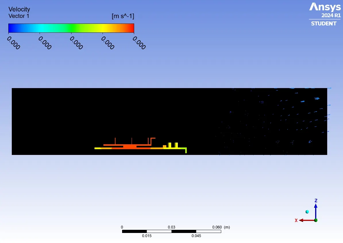
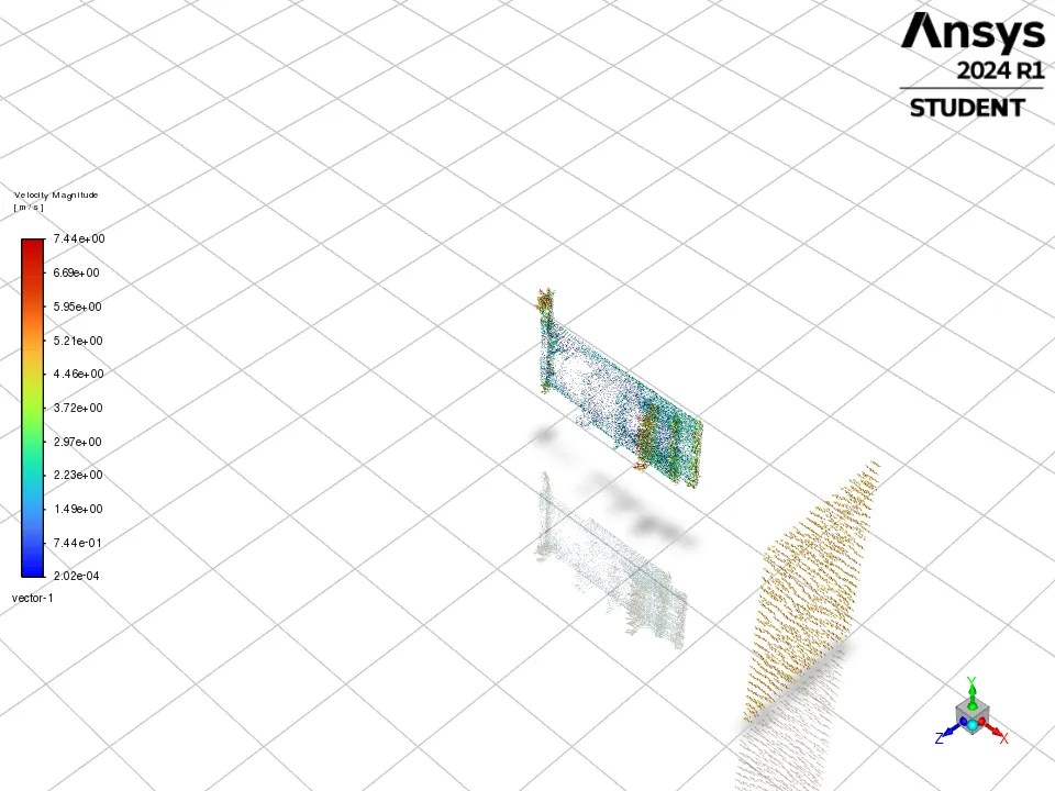
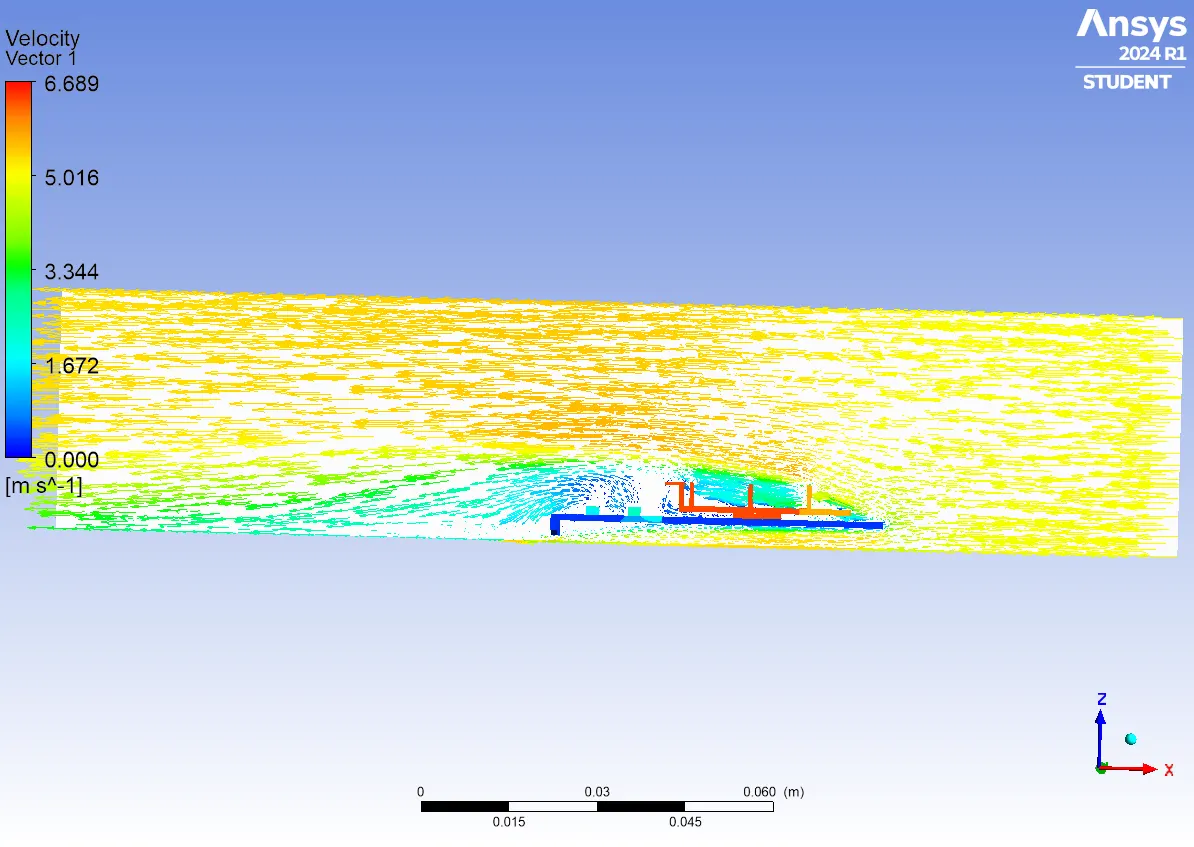
VECTORS :
PLOTS :
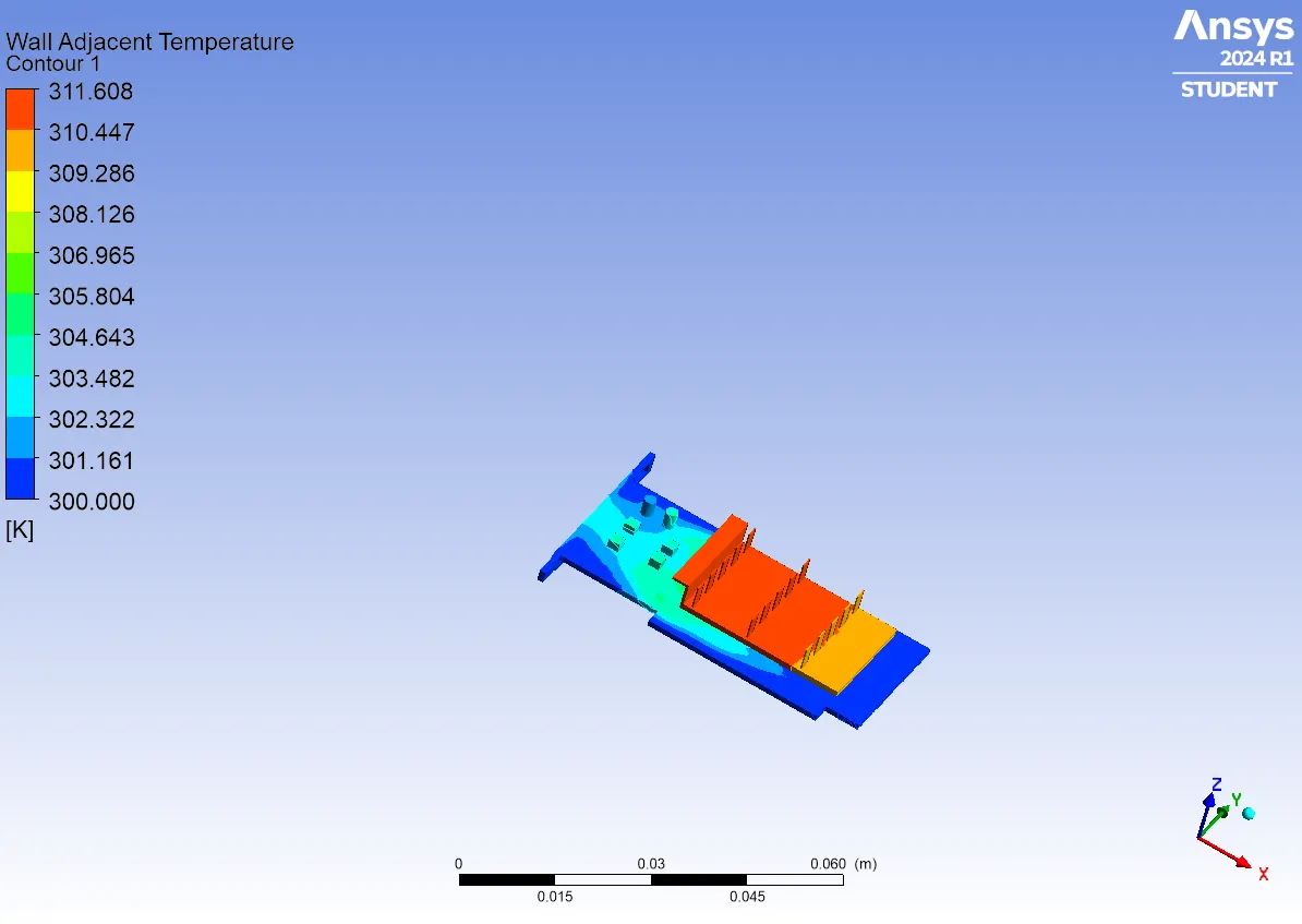
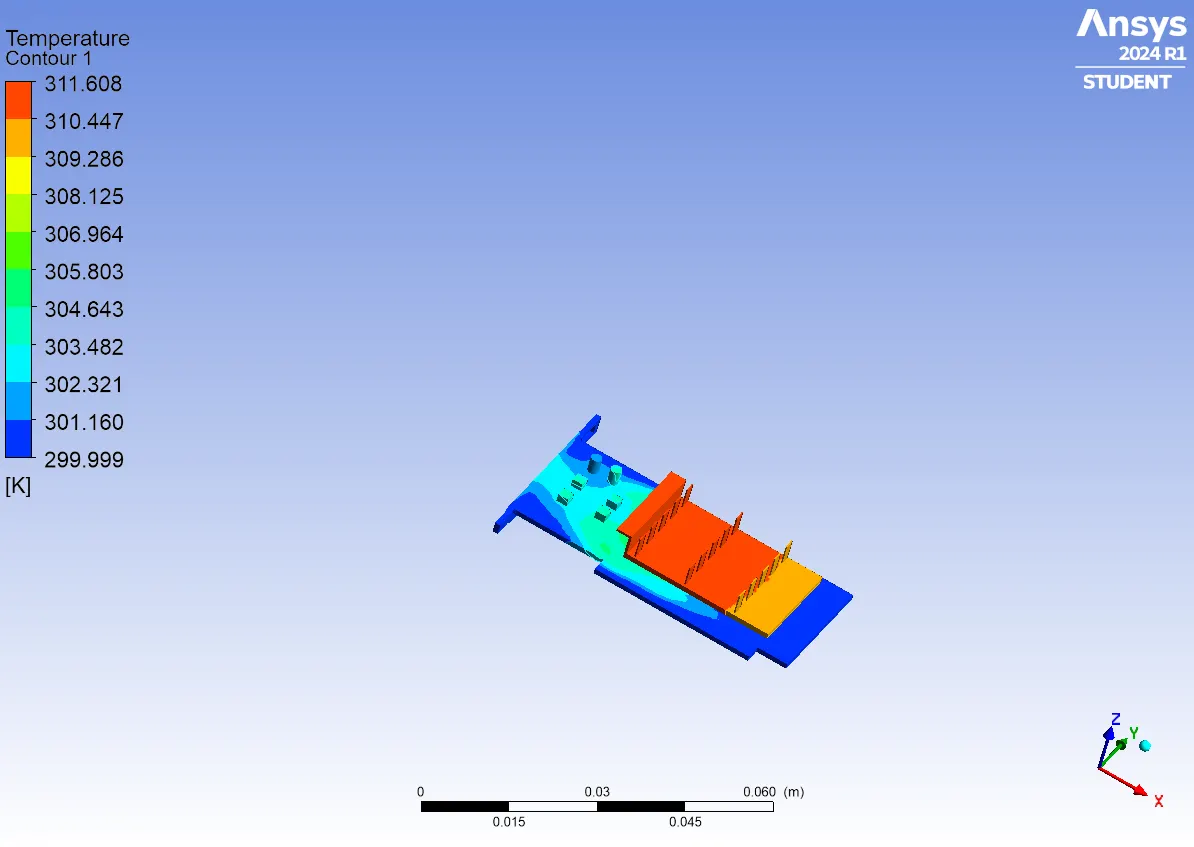
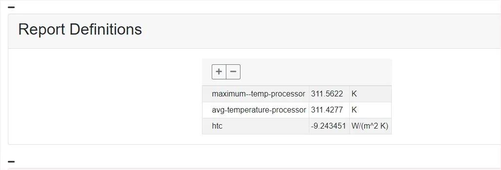
REPORT DEFINATIONS :
BASE MESH

REFINED WITH VELOCITY 1M/S
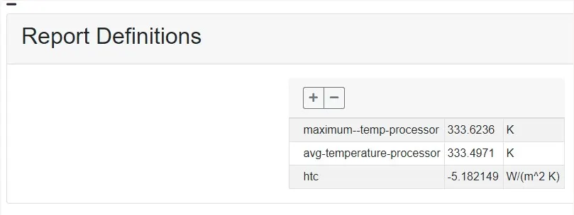
REFINED WITH VELOCITY 3M/S
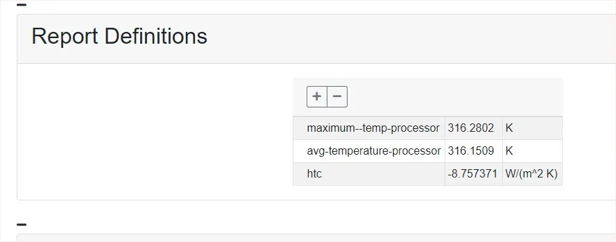
REFINED WITH VELOCITY 5M/S
CONCLUSION :
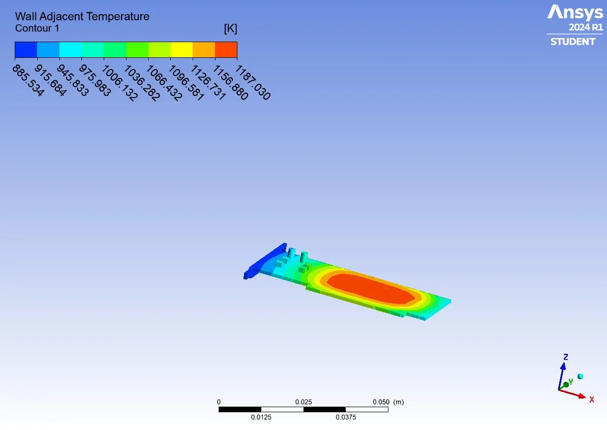
A Converged Solution For The Given Sets Of Input Was Observed On The Basis Of Repetitive Plots In The Residual Plot. The Processor Acted As A Source Of Heat Input And Thus One Of The Hotspots For Such Study With An Increase In Velocity, We Saw A Considerable Drop In Temperature And A Substantial Rise In Heat Transfer Coefficient Which Shows That High-Velocity Air Can Be An Effective Mode Of Heat Dissipation In Graphics Card From The Temperature Distribution, We Can See Hotspots In The Fin And Base Near The Surface That Is In Contact With The Processor. Based On The Thermal Conductivity Of The Material This Temperature Is Distributed Accordingly Amongst The Component. We See A Few High-Temperature Zones On Fin Away From Processor Depicting Their High Susceptibility To Heat Due To Their Geometry. Also, The Difference In Baseline And Refined Mesh Is Considerable And Thus We Can Conclude That More Refined Mesh Provides A Better Solution And Can Be Used In Optimizing The Design For Such Applications From The Residual Plot, The Change In The Gradients Is Very Small With Which We Can Conclude That The Solution Has Converged. From The Temperature Plot Of The Coarse Mesh, The High-Temperature Points Are Found At Fins, Processor, And Base Area Near The Processor. As The Wall Heat Transfer Coefficient Is A Wall Phenomenon And Fins Dissipate A Large Amount Of Heat Which Results In Higher Heat Transfer Co-Efficient But The Coarse Mesh Heat Transfer For Fins And Other Components In The Graphics Card Has The Same Values. Hence Refinement Of Mesh Is Done For Fins And Base Of The Fin And Base Of The Graphic Card In Order To Calculate The Wall Heat Transfer Coefficient At The Fins And Base. The High-Temperature Regions Are Found At The Centre Of The Fins, Base, And The Processor Walls. With Further Iterations, The Temperature Is Distributed To Other Regions In The Graphics Card In The Direction Of The Inlet Airflow. Conduction Occurs Where There Is A Contact Region Between The Solids In This Case It Is Between Processor And Fins And Processor And Base. Convection Occurs When The Heat Generated In The Components Of The Graphic Card Is Removed By The Inlet Airflow. The Maximum Temperature In The Components Is Inversely Proportional To The Inlet Airflow Velocity. With The Increase In The Airflow Velocity, The Heat Removal Process By Convection Is Faster. And Also Recirculation Of Air (Vortex) At Appropriate Places Will Increase The Heat Transfer Efficiencies Hence Greater Amount Of Heat Is Removed By Convection.