Week 2 Challenge : Surface meshing on a Pressure valve
AIM: To create a fine mesh on a pressure valve
OBJECTIVE:
- To avoid or eliminate the geometrical errors and perform a topolgy cleanup
- to set three different target lengths aa three different cases and to mesh the model
REQUIREMENTS:
- Target length = 1mm, 3 mm and 5 mm (i.e. 3 cases)
- Element type = Tria
PROCEDURE:
- Open the ansa software
- import the model
- press ctrl+shift>to view the wire frame and visualise the erros called single cons and triple cons>esc.
- click cross sction to turn on or off the cross sections>esc.
- click peirm to turn on or off the single,double,triple cons>esc.
- click shadow and wire to view the model in wire frame or solid>esc.
- cliick on not,and to hide and unhide the model>esc.
- click on all to retrive the entire model at a time>esc.
- click on lock to lock or freeze the interface.>esc.
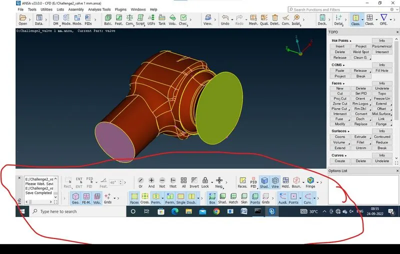
- select views section>select isometric view> clickon>esc>to visuailise the model in a 3D
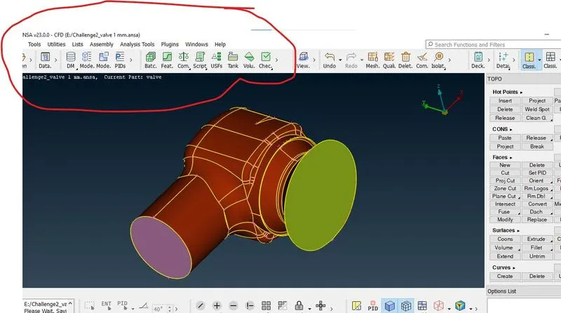
- select checks section> select checks manager>excute>double click on >esc>to find and view the geometrical errors and intersection.
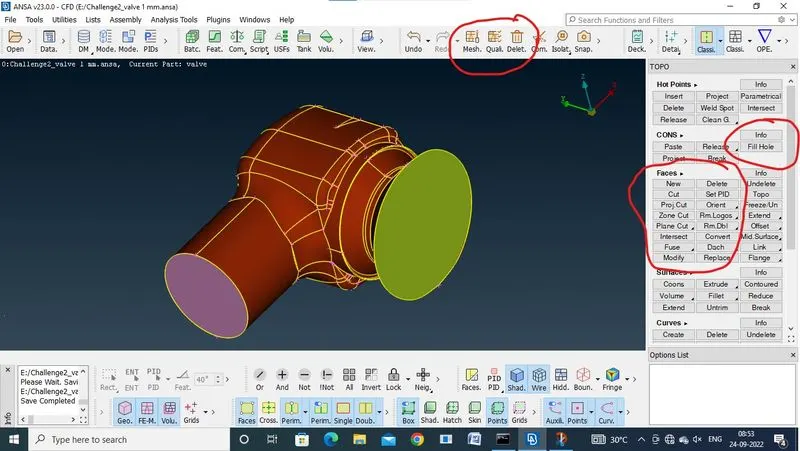
- click on topo section>select faces >click new>to generete the coons,fitted,planar,and existing surfaces,to use eliminate errors>select cons>middle click>esc.
- select delete >to delete unwanted sections or faces>select face>middle click>esc.
- click on cons > select the fill hole to fill the entire error on surface>select cons>middle click>esc.
-
- click on pid properties>right click>click on new>>click on shell property>create the shell propertys with names> assign colors if needed>select cross scetion or face >middle click >to assign the pid>esc.
- use pid's to hide or unhide the parts or shells>click on bulb>esc.
- select intersect >select the 1st face>middle click>select 2nd face>middle click>delete or keep the faces if needed>esc.
- select the cut>select cons>select face> middle click>esc.
- click topo>select the model>middle click>esc>to avoid erros and joins the cons.
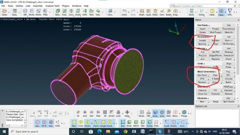
- click om mesh section>select perimeter>click on length>click on perimeter >select model>add lengthg>middle click >click macros>select model>middle click>esc.
- click on mesh >add max length>add min length>put cfd mesh>keep tria>ok>esc.
- click quality >add max length>add min length>ok>esc.
- click compress >click ok>esc.>to remove unwanted shells.
- select generate mesh>click cfd or spot>select visible>mesh completed.
- change the lengths to increase the quality of the mesh.
LEARING OUTCOMES:
- how to use topo command on model.
- how to use intersect command on model.
- how to use new command on model.
- how to use cfd command on model.
- how to use pid command on model.
- how to use checks command on model.
- how to use views command on model.
- how to use universal delete command on model.
- how to use lock command on model.
- how to use fill hole command on model.
- how to use quality command on model.
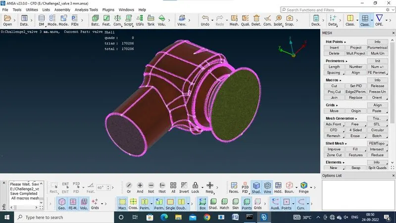
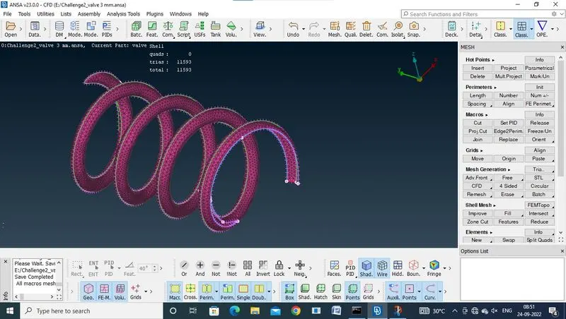
RESULTS:
5MM MESH MODEL:
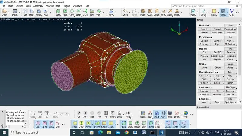
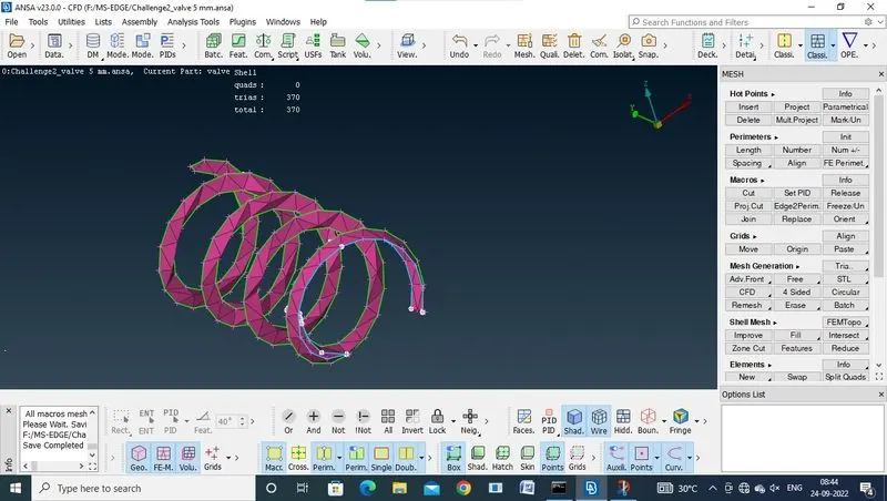
3MM MESH MODEL:
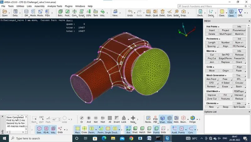
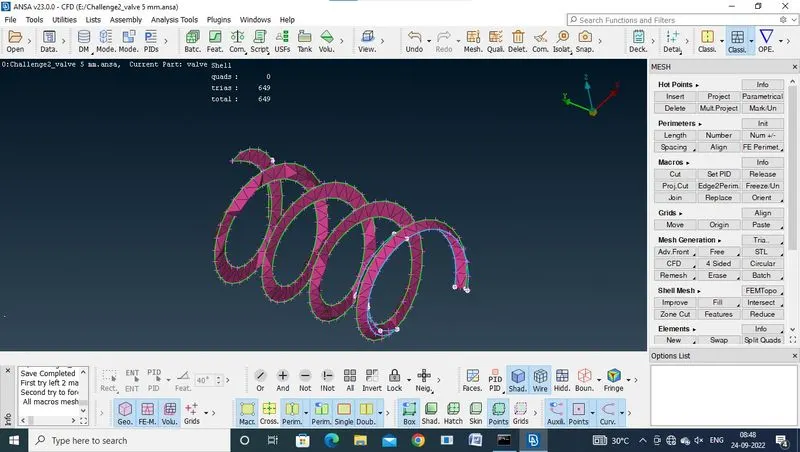
1MM MESH MODEL:
CONCLUSION:
when the quality of the mesh increased the length of the element were decreased and its take compactability time when the length decreased,to mesh the model.
LINKS:
https://drive.google.com/file/d/1o2Px0e9U2NOQ-fVD8qoid-cZmhdUKHOp/view?usp=sharing
https://drive.google.com/file/d/1giOzRaUYGAhHG1J-c9bsOknUCgBlWiXg/view?usp=sharing
https://drive.google.com/file/d/1uEt4uN_brTrC3tEOFy7TVDvIpC-rkA7w/view?usp=sharing