Week 7 - CHT Analysis on a Graphics card
CHT ANALYSIS OF GRAPHIX CARD
AIM -To annalyse and study the steady-state conjugate heat transfer for the graphix card models at various air flow speed to the heat transfer rate and temperature variation generated
CONJUGATE HEAT TRANSFER
Conjugate heat Transfer annalyis also known as CHT annalyis is the heat transfer between two domains by exchange of thermal energy. For a system the thermal energy available is defined by its temperature and the movement of thermal energy is defined by its heat flux through the outer walls. Heat transfer in solid happens through conduction and walls by convection and in liquid phase through convection. We can annalyse various parameters of heat exchange from these study as well as temperature distribution
SIMULATION AND PROCESS
We will analyse the steady-state annalysis on the graphix card for a coarse as well as refined mesh at different velocities that are 1,3,5 m/s respectively
DESIGN SETUP
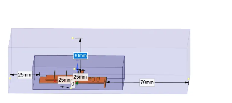
The design of the graphix card was downloaded .The first step was to generate the enclosure for the graphix card which was based on the dimensions .
The design was segregated to diffenet componenets like the enclosure and the graphix card was seperated
we will also assign the share topology for the graphicx card and the enclosure
SETUP AND MESHING
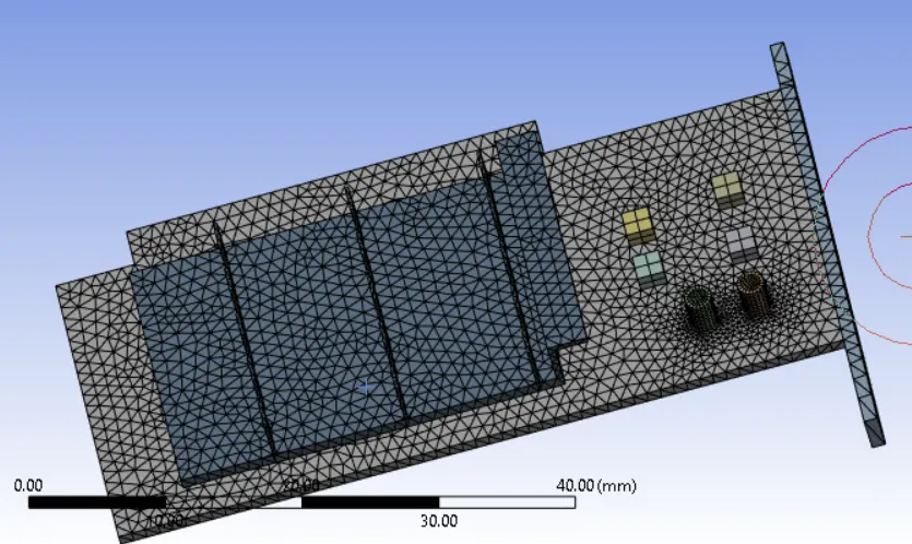
The design was openened in the meshing and we will then name the various parts of the design like the inlet,outlet,boundary ,fins,processor and base .The meshing was undertaken in two forms
Note- due to software and system issue meshing was not able to be performed properly for the coarse meshing
Refined Meshing
the meshing was refined and the updated mesh was used for the annalysis
mesh details (refiened )
Enclosement- mesh element size-8mm
Graphix card -mesh element size -1mm
SETUP
Material selection
The material selected for the various components of the graphix card were
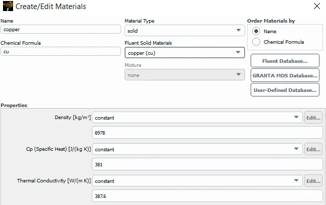
Fins
Copper solid material with the specication as mentioned in the below image
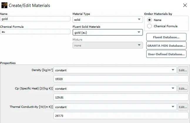
Chipset
Gold was selected as solid for the chipset with the specification as mentioned in the below image
Base
wood solid was selected for the base with the specifications
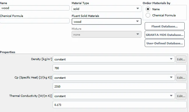
fluid material was air
The heat source was chipset with a value of 15680000 W/m2 heat produced during its working
RESULTS
no of iteration=200
time factor=0.025
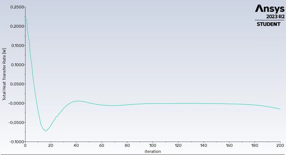
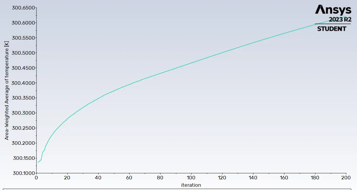
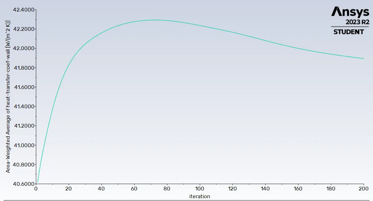
1.For air speed of 5m/s with temperature of 300 K
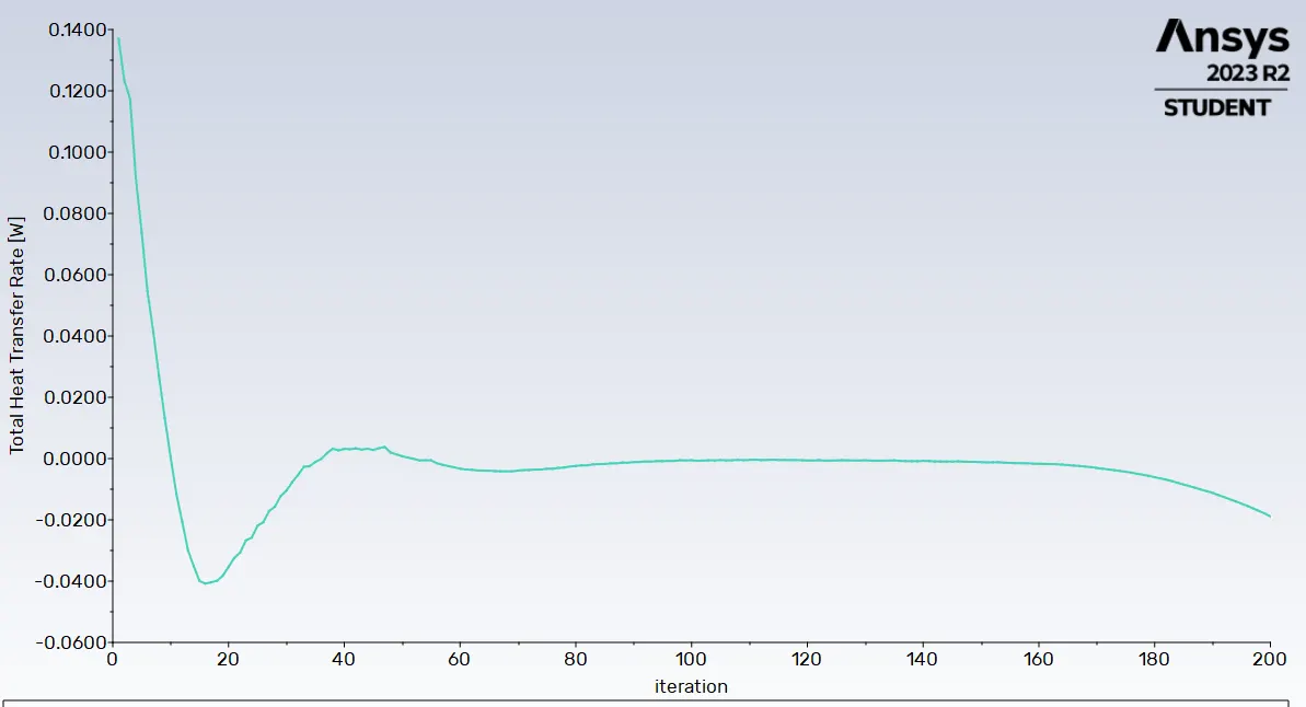
Heat transfer rate plot
Area Weigted Average of Temperature
Heat transfer coefficient wall
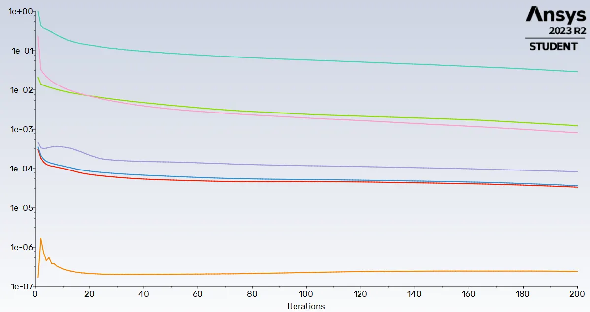
Residuals convergence
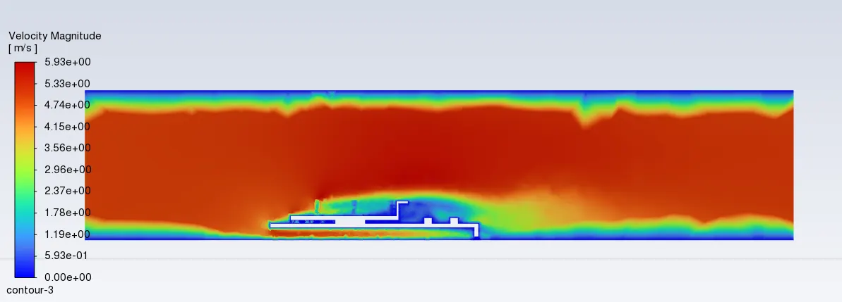
Velocity contour over a plane selected
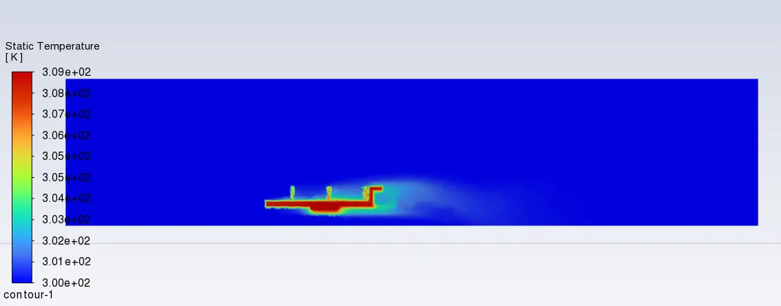
Temperature
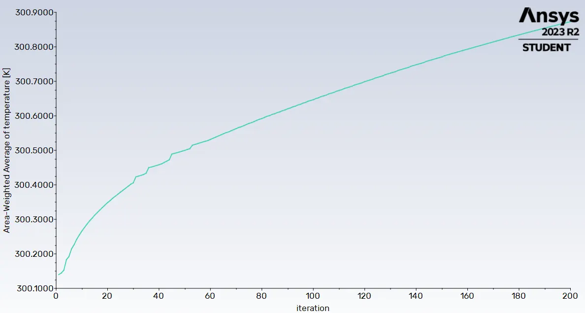
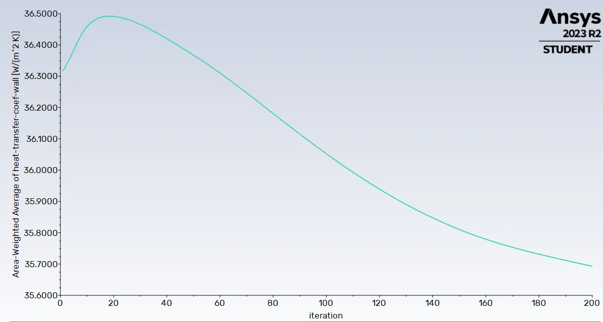
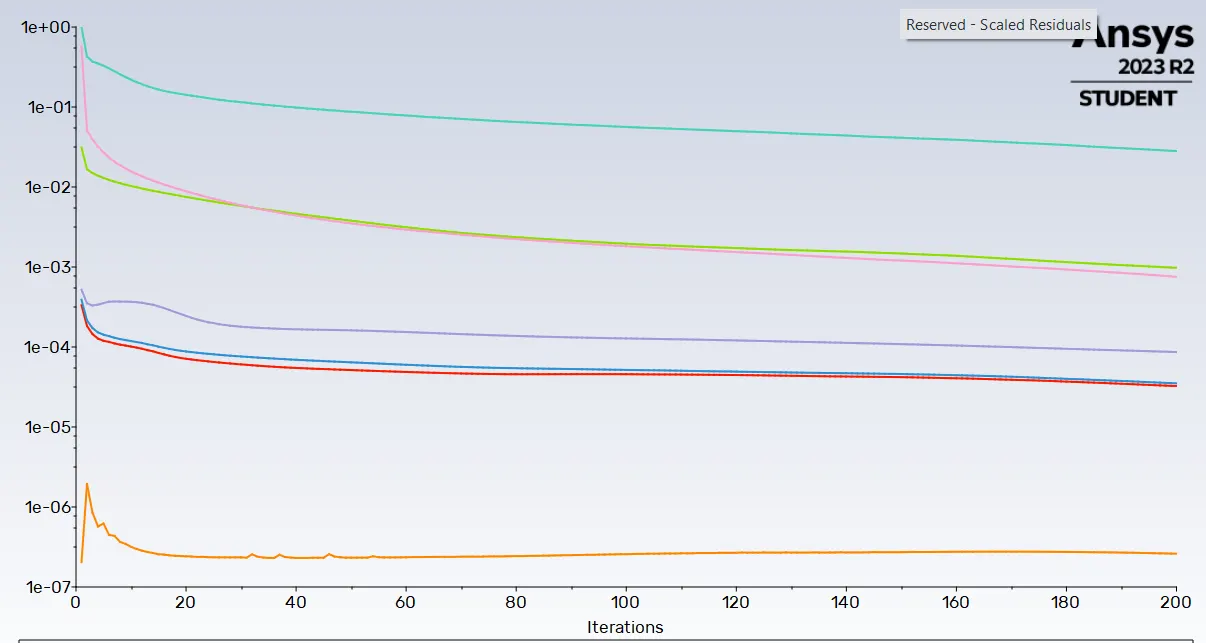
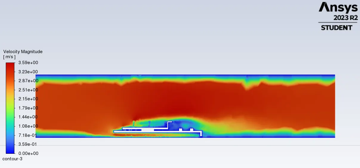
2. With velocity of 3m/s at 300 K
Heat transfer rate plot
Area Weigted Average of Temperature
Heat transfer coefficient wall
Residuals convergence
Velocity contour over a plane selected
Temperature
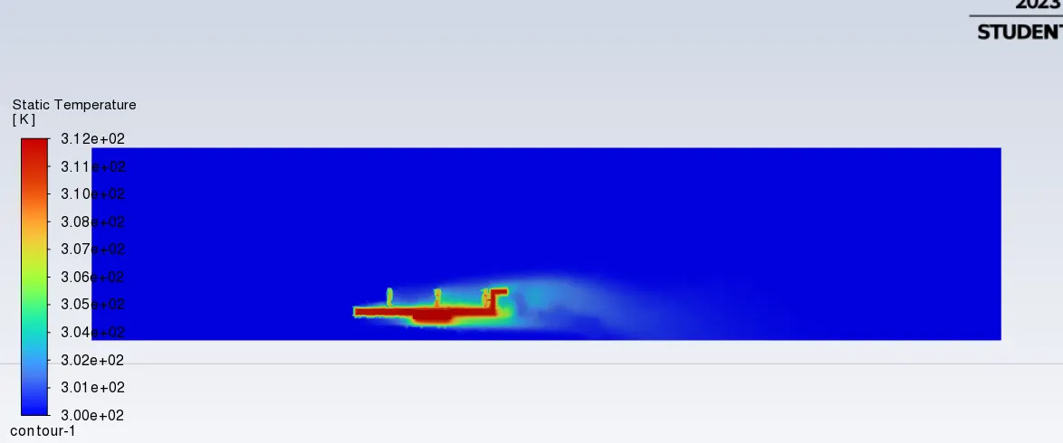
3.With velocity of 1m/s at 300 K for 250 iteration
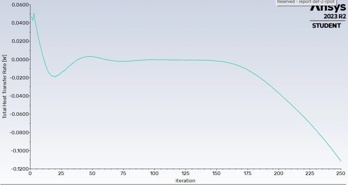
Heat transfer rate plot
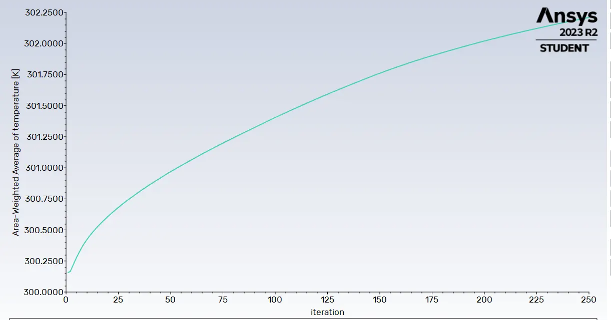
Area Weigted Average of Temperature
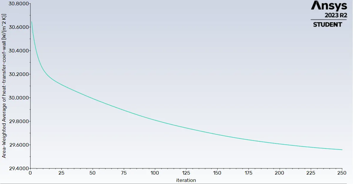
Heat transfer coefficient wall
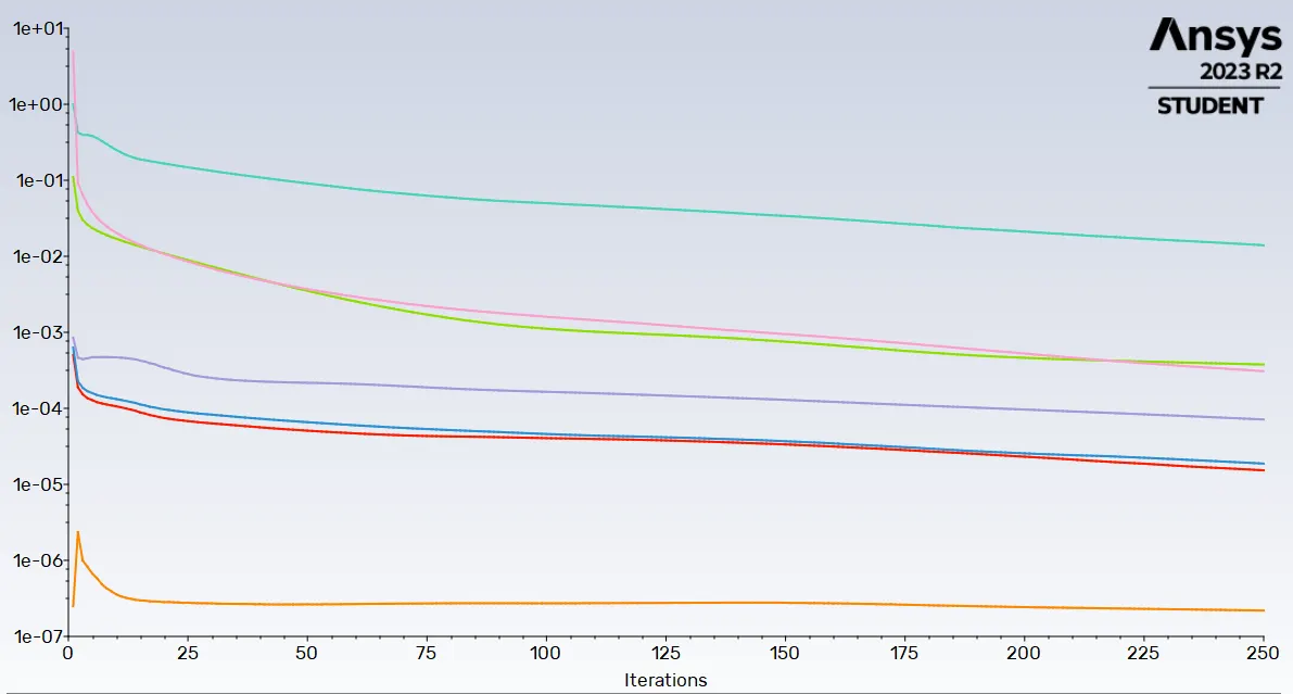
Residuals convergence
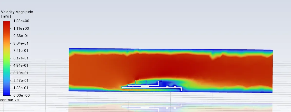
Velocity contour over a plane selected
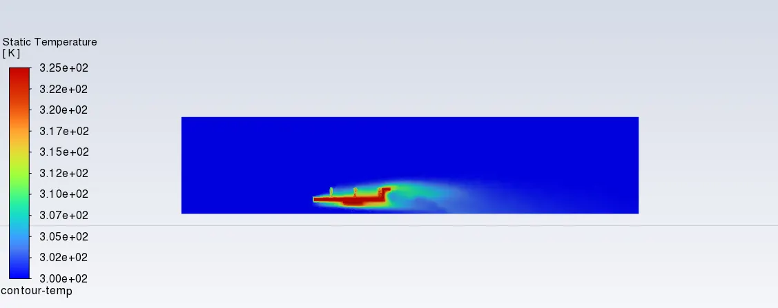
Temperature
CONCLUSION
| Velocity m/s | Temperature processor | temperature at fins | Heat transfer coeff |
| 1 | 325 | 315 | 29.6 w/m^2 K |
| 3 | 312 | 307.6 | 35.70081 W/m^2 K |
| 5 | 309.8 | 305 | 42.0096 W/m^2 K |
From the above results we were able to conclude the variation in various parameters measured during thr CHT annalysis
*The net temperature of the components of the graphix card decrses with the increase in the flow velocity of the working medium that is air
*The high rate of air flow increases the heat transfer coefficient of the syatem thus helping in effective heat dissipation from the system to the surrounding
*Increasing the mesh quality will improve the results of the annalysis and help in determining more accurate results of the temperature distribution