Week-7 Challenge: DC Motor Control
1.
A.Explanation of Demo Model:
This demo model can be found in the matlab documentation tab under the name of 'Speed Control of a DC motor using BJT H-bridge'
First of all the dc motor is modelled using simulink block dc motor and with the help of ideal rotational motion sensor the speed is measured and here we are using fan type load for this using the relation T=K*W^2 and torque sensor the load is realised and connected to the motor
Next Using the BJT the H-bridge model is realized and here for simplicity we have used IGBT because when BJT under forward biased condition resembles the IGBT
In the H-bridge model the first , third should not operate at the same time if it operates short circuit will happen because both are in the same leg likewise second , fourth also should not operate , at a time first and fourth should operate and second and third should operate for forward condition and reverse condition respectively .
The above condition can be realised using the step signal and pulse generator and switch and it is given to the gate of the four IGBT and our condition in positive cycle the one and four should forward bias and in negative cycle two and three is forward bias respectively is met .
B. Comments on the 'Armature Current Shoot-up':
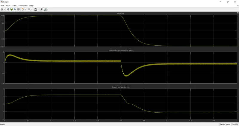
The armature current in the motor shootup initially at time t=0 because when the conduction of switches are happening there will be sudden inrush of current to rotate the motor to its rated speed after that it will settle and at t=0.5 another reverse cycle will happen so there is a shoot down occuring in the scope results . this is purely based on the switch characteristics and its response time , due to the switching transients also.
C. Comparison between four quadrant operation and H-bridge model:
Four quadrant operation H-Bridge model
1. operating in discrete mode 1.operating in continuous mode
2. speed reference is used 2.not used
3. transients are reduced and there is a smooth operation 3.there is no smooth operation sudden shoot up and down while switching
4. uses a pwm technique to operate 1 and 4 , 2 and 3 appropriately using 4.it uses a threshold voltage for a microcontroller device so switching is accurate switching operation
The demo model is attached below in the filename of 'power_Hbridge_BJTModel1.mdl' and 'dc7_example41.mdl' respectively for your reference.
2. 2-Quadrant Chopper :
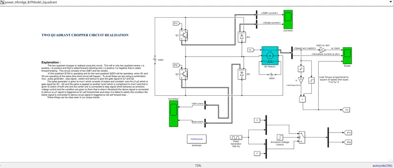
Explanation :
The two quadrant chopper is realised using this circuit , This will in only two quadrant where v is positive, I is positive and that is called forward motoring and v is positive I is negative that is called forward braking . This circuit consists of two IGBT and two diodes .
In first quadrant Q1D4 is operating and for the next quadrant Q2D3 will be operating when Q1 and Q2 are operating at the same time short circuit will happen . To avoid these we are using a combination mux , pulse generator , step signal , switch and demux to give the gate signal to Q1 and Q2 .
The pulse generator is given to mux1 which consists of pulses and constant zero for p1,p2 which is gate signal for Q1 , Q2 and the same is applied to another mux2 which is compliment to mux1 and that is given to switch of both end and the center one is connected to step signal which behaves as armature voltage control and the condition are given to them that is when>=threshold the above signal is connected to demux so p1 signal is triggered so Q1 will forward bias and when it is failed to satisfy this condition the below signal is connected to demux so p2 signal is triggered so Q2 will forward bias ..
These things can be clear seen in our scope results .
Scope Results:
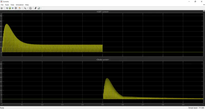
The above one is Q1 and D3 current waveform.
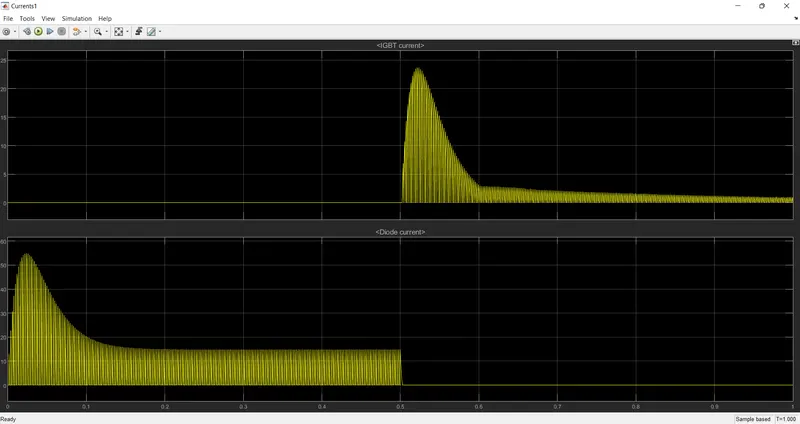
The above one is for Q2 and D4 current waveform.
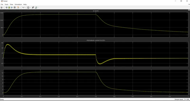
The above one shows the results of speed , torque and armature waveform
The model file is attached below under the filename of 'power_Hbridge_BJTModel_2quadrant1.mdl'
3. Operation of a BLDC Motor :
The BLDC stands for BrushLess DC Motor unlike a dc motor where a commutator and brush is used to reverse the current here in BLDC an electronic commutation is used to operate the motor continuously
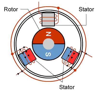
The above diagram shows how the BLDC motor was operating
In this example the stator consists of three coils u,v,w and rotor is a permanent magnet . with the help of electronic controller we are going to change the phase sequence that is we are energizing the two coils out of three so that the resultant which is a vector addition of two will be getting in one direction based on that the motor will be moving in clockwise or counter clockwise direction
so in this we have seen that we are using six step pulse for smooth operation of motor .
Controlling the Magnetic Field
To rotate a BLDC motor, one needs to control the direction and timing of the current into the coils. Figure 2(a) illustrates a BLDC motor’s stator (coils) and rotor (permanent magnets). Let’s use this illustration to see how the rotor is made to turn. In this example we are using three coils, whereas in practice it is more common to use six or more. But here we look at just three coils, spaced at 120º. A motor, as we noted in our last session, performs the task of converting electrical energy into mechanical energy. So how does the motor in our illustration do this? Let’s look at what goes on inside.
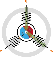
Figure 2(a): BLDC Motor’s Principle of Rotation.
Typical configuration: three coils with 120º spacing. Driven by controlling the phases and coil currents.
For our example, we show a 3-coil motor. Let’s label the coils U, V, and W. Remember that the passing of a current through a coil generates a magnetic field. Since there are three coils, there are three paths through which we can pass current; we can call these phase U (current into coil U), phase V (into coil V), and phase W. Let’s look first at phase U. If current moves through U only, magnetic flux is generated as shown by the arrow in Fig. 2(b). In actuality, all three coils are interconnected, through a single lead wire from each—and it is not possible to generate phase U in isolation. Figure 2(c) shows what happens when current moves through coils U and W (phase “UW”), with the arrows again showing the flux generated at each coil. The wide arrow in Figure 2(d) is the resultant flux—the result of the combined magnetic fields from U and W. This large flux will cause the inner rotor to turn until the S and N poles of the rotor permanent magnet are aligned on this arrow (with the N pole closest to the arrow tip).
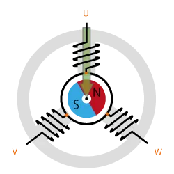
Figure 2(b): BLDC Motor Principle of Rotation.
Current flows through U and then W. The arrow shows flux generated by coil U.
Figure 2(c): BLDC Motor Principle of Rotation.
Current flows through U and W. The two arrows show flux generated by coils U and W, respectively.
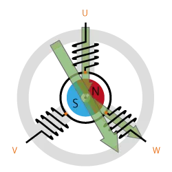
Figure 2(d): BLDC Motor Principle of Rotation.
The wide arrow shows the resultant flux—the sum of the flux produced by U and W.
Rotation is maintained by continually switching the flux so that the permanent magnet is constantly chasing the rotating magnetic field induced by the coils. In other words, energizing of U, V, and W must be continually switched so that the resultant flux keeps moving, producing a rotating field that continually pulls on the rotor magnet.
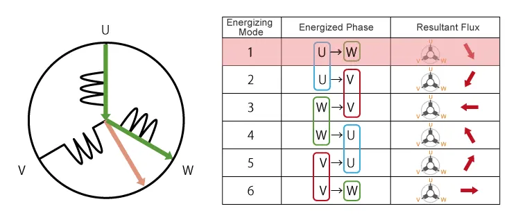
Figure 3 shows the relationship between energized phases and flux. As you can see, switching sequentially through modes 1 through 6 will cause the rotor to turn clockwise through one rotation. The speed of rotation can be controlled by controlling the rate at which the phases change. We use the name “120-degree conducting control” to the 6-mode control method described here.
Sinusoidal Control Delivers Smooth Rotation
With 120-degree conducting control, there are only six resultant flux directions for driving the motor. For example, switching from Mode 1 to 2 (see Fig. 3) moves the resultant flux direction by 60º, pulling the rotor along accordingly. Switching from Mode 2 to 3 shifts the flux direction another 60º, again pulling the rotor. Repeating this process generates a continuous rotation, but it is a somewhat jerky rotation. In some cases, this jerkiness will create unwanted vibrations and mechanical noise.
As an alternative to 120-degree conducting control, we can use sinusoidal control to achieve smoother and quieter operation. With 120-degree conducting control, the motor is controlled by continually cycling through six fixed resultant fluxes. And as you can see in Figure 2(c), U and V both generate fluxes of equal magnitude. By more carefully controlling the current into U, V, and W, however, we can generate differing flux magnitudes at each coil, allowing us to more precisely vary the resultant flux. (See Fig. 4.)
By carefully adjusting the current flow into each of the three phases, then, we can achieve a more continuous change in resultant flux, resulting in smoother motor rotation.
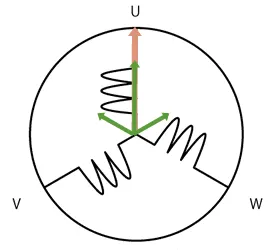
Figure 4: Sinusoidal Control.
By controlling the current into all three phases, resultant flux magnitude and direction can be controlled more precisely that with 120-degree conducting control, so as to achieve smoother rotation. Resultant flux is no longer limited to six discrete directions.
Control by Inverter
Let’s look again at the nature of the current into U, V, and W. For simplicity, let’s see how this works with 120-degree conducting control. Looking back to Figure 3, we see that in Mode 1 the current flows from U to W; in Mode 2, from U to V. As the arrows in the figure show, each change in the energized coil combination causes a corresponding change in the flux direction.
Now look at Mode 4. Here we have current moving from W to V; this is the just the reverse of Mode 1. With a brushed DC motor, this type of current reversal would be achieved using brushes and commutator. BLCD motors cannot by definition use brushes or other mechanical contact to achieve this reversal. Instead, they generally use inverter circuitry to implement this control.
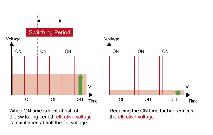
And by using the inverter circuitry to also adjust the voltage into each coil, we can in addition control the magnitude of the current. A typical way to adjust the voltage is with pulse width modulation (PWM). In this approach, we alter the voltage by lengthening or reducing the pulse ON time (also referred to as the “duty cycle”: the ON time expressed as a ratio of the ON+OFF switching interval). Increasing the duty cycle has the same effect as raising the voltage; reducing the duty cycle has the same effect as lowering the current. (See Fig. 5.)
PWM can be implemented using MPUs equipped with dedicated PWM hardware. While 120-degree conducting control only requires two-phase voltage control and be implemented relatively easily in software, sinusoidal control uses three-phase voltage control and is considerably more complicated. Appropriate inverter circuitry is therefore essential for driving BLDC motors. Note that inverters can also be used with AC motors. But when a term such as “inverter type” is used with reference to consumer electronics, it is usually referring to a BLDC motor.
Hall Sensors
Hall sensor provides the information to synchronize stator armature excitation with rotor position. Since the commutation of BLDC motor is controlled electronically, the stator windings should be energized in sequence in order to rotate the motor. Before energizing a particular stator winding, acknowledgment of rotor position is necessary. So the Hall Effect sensor embedded in stator senses the rotor position.
Most BLDC motors incorporate three Hall sensors which are embedded into the stator. Each sensor generates Low and High signals whenever the rotor poles pass near to it. The exact commutation sequence to the stator winding can be determined based on the combination of these three sensor’s response.
Brushless DC Motor Drive
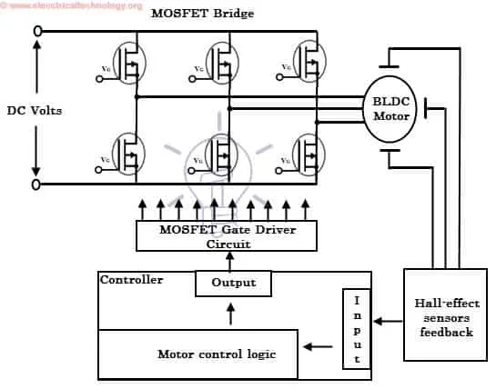
As described above that the electronic controller circuit energizes appropriate motor winding by turning transistor or other solid state switches to rotate the motor continuously. The figure below shows the simple BLDC motor drive circuit which consists of MOSFET bridge (also called as inverter bridge), electronic controller, hall effect sensor and BLDC motor.
Here, Hall-effect sensors are used for position and speed feedback. The electronic controller can be a microcontroller unit or microprocessor or DSP processor or FPGA unit or any other controller. This controller receives these signals, processes them and sends the control signals to the MOSFET driver circuit.
In addition to the switching for a rated speed of the motor, additional electronic circuitry changes the motor speed based on required application. These speed control units are generally implemented with PID controllers to have precise control. It is also possible to produce four-quadrant operation from the motor whilst maintaining good efficiency throughout the speed variations using modern drives.