Q1. Power converters employed in hybrid and electric vehicle :
AC to DC converters known as rectifiers is used in EV charger applications and DC to AC converters known as inverter used in motor drive applications , DC to DC converters known as choppers used for stepup and stepdown purposes, it is generally used to power up auxillary devices used in the electric vehicle and AC to AC known as cycloconverters used for reducing the frequency of AC or increasing it .
Mainly , in electric vehicle we are using DC-DC power converters and this is explained below as follows :
The different configurations of EV power supply show that at least one DC/DC converter is necessary to interface the FC, the Battery or the Supercapacitors module to the DC-link.
In electric engineering, a DC to DC converter is a category of power converters and it is an electric circuit which converts a source of direct current (DC) from one voltage level to another, by storing the input energy temporarily and then releasing that energy to the output at a different voltage. The storage may be in either magnetic field storage components (inductors, transformers) or electric field storage components (capacitors).
DC/DC converters can be designed to transfer power in only one direction, from the input to the output. However, almost all DC/DC converter topologies can be made bi-directional. A bi-directional converter can move power in either direction, which is useful in applications requiring regenerative braking.
The amount of power flow between the input and the output can be controlled by adjusting the duty cycle (ratio of on/off time of the switch). Usually, this is done to control the output voltage, the input current, the output current, or to maintain a constant power.
Design consideration requirements of converters employed in electric vehicle:
-
light weight,
-
High efficiency,
-
Small volume,
-
Low electromagnetic interference,
-
Low current ripple drawn from the Fuel Cell or the battery,
-
The step up function of the converter,
-
Control of the DC/DC converter power flow subject to the wide voltage variation on the converter input.
Q2.
%Matlab code :
%Steady state of EV vehicle with the motor characteristics
% Torque speed relation of EV vehicle
% Equation : Tv=24.7+(0.0051)W^2
% Torque-speed relation of DC motor
% Wm=d*Vt/(K_phi)- (Ra/(K_phi)^2)*T
% The intersection between the Ev plot and the motor plot is known as the
% steady state and it is considered to be the region where we can the
% operate the electric vehicle more conveniently
W=linspace(0,50,1000); % W - angular speed of electric vehicle
Tv=24.7+(0.0051)*W.^2; % Tv - Torque of electric vehicle
%Giving input to the variables
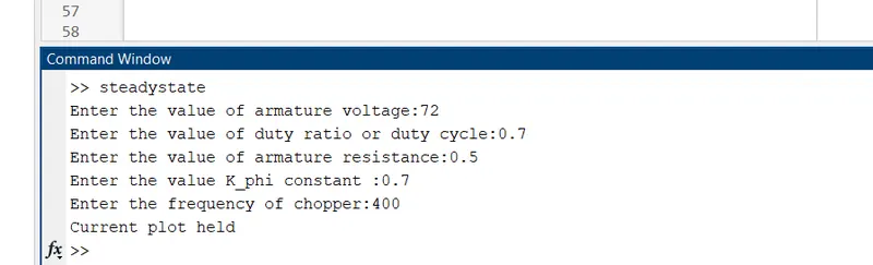
Vt=input('Enter the value of armature voltage:');
d= input('Enter the value of duty ratio or duty cycle:');
Ra=input('Enter the value of armature resistance:');
K_phi=input('Enter the value K_phi constant :');
f=input('Enter the frequency of chopper:');
t=(1/f);
Wm=linspace(0,50,1000); % Wm - angular speed of dc motor
T= ((d*Vt/(K_phi))-Wm)*((K_phi)^2/Ra);%converting the equation wm to T
% T- Torque of dc motor
%plotting the torque-speed characteristics of electric vehicle
plot(Tv,W,'m');
ylabel('Angular Speed(w) - RPS');
xlabel('Torque - Nm');
title(' Torque - Speed characteristics of electric vehicle ');
%plotting the torque-speed characteristics of separately excited dc motor
figure(2);
plot(T,Wm,'b');
ylabel('Angular Speed(w) - RPS');
xlabel('Torque - Nm');
title(' Torque - Speed characteristics of Separately excited dc motor ');
%plotting the intersection region
figure(3);
plot(Tv,W,'m');hold ;
plot(T,Wm,'b');
v=[0 70 0 60];
axis(v);
ylabel('Angular Speed(w) - RPS');
xlabel('Torque - Nm');
title(' Steady-State operating region ');
Results:
Explanation:
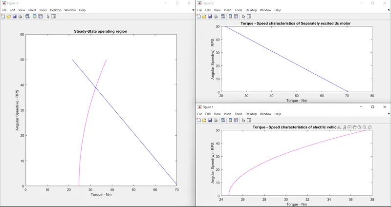
The above matlab program produces the intersection characteristics , The steady-state speed is found to be around 38.8 rps which is found to be around 370 RPM
The matlab file is attached below in the file name as 'steadystate.m'
Q3:
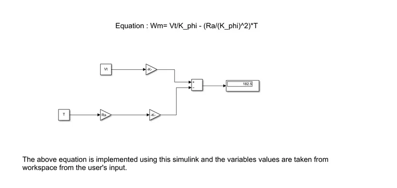
simulink model:
% Matlab code for giving values to the variables being used
% Taking the values of the variables used in simulink using this script
count=0;
while count==0
Vt=input('Enter the voltage value (Vt):');
K_phi=input('Enter the constant value (K_phi):');
Ra=input('Enter the armature resistance value (Ra):');
T=input('Enter the Torque value (T):');
count=count-1;
end
Results:
Explanation:
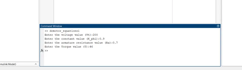
I have here showed you the input details and the output value of w in the form of screenshot in the above results
the matlab code is attached in the filename as 'dcmotor_equations1.m'
the simulink file is attached in the filename as 'dcmotor_equations2.mdl'
Q4 : Explaining the author perspective about DC brushless motor versus Induction motor :
The author perspective about DC brushless motor versus Induction motor is both the motor has a certain advantages and limitations when they are coming into live action , but both machine drives are similiar that is both uses 3 phase modulator inverter circuits, they will not become obsolete as their performance was very higher
In construction wise:
according to the construction , both machines are having a stator and the current is passed to the stator , but the difference is incase of dc machine rotor has made of PM , because it is dc the current is changed alternatively so that it interacts with rotor magnetic field and produces a torque with the help of current control inverter
when coming to the induction motor , due to the stator magnetic field and its interaction with the rotor , a current will flow to the rotor bar which inturns produces voltage and there is a speed difference therefore the motor rotates
Efficiency wise:
The brushless dc motor drive has comparable lower efficiency compared to induction drive because in dcmotor drive magnetic field intensity can't be adjustable easily so losses will be more but in case of induction drive it is adjustable by using v/f control when torque is low voltage is reduced so noload losses will be reduced , when torque is higher , full load losses are reduced by increasing voltage , thus efficiency is increased
Control :
The dc brushless motor is easily controllable but in case of induction motor , it requires a very complex control circuit to control the motor