Week-7 Challenge: DC Motor Control
1. A. Explain a MATLAB demo model named ‘Speed control of a DC motor using BJT H-bridge’.
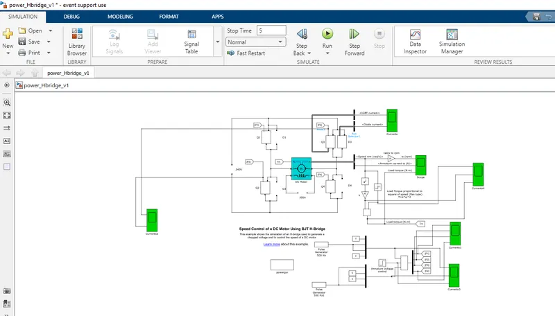
- Load Torque proportional to square of speed (Fan type) T=k*w^2
- Here we are using a fan load
- In this we are using a 4 igbts in h-bridge configuration
- Matlab simulation time i set was 7 sec
- For first 0.5 sec the motor running in forward direction and another 6.5 sec motor runs in reverse direction
- The motor direction run can be changed by changing the value in switch which is used in PWM inputs
- P1 and P4 pulse for forward direction.
- P2 and P3 pulse for reverse direction
- The duty cycle was set 75 %
- Armature voltage is equal to rated voltage * duty cycle.
- Rated voltage=230 V DC
- Armature voltage = 230*0.75 = 172 V DC
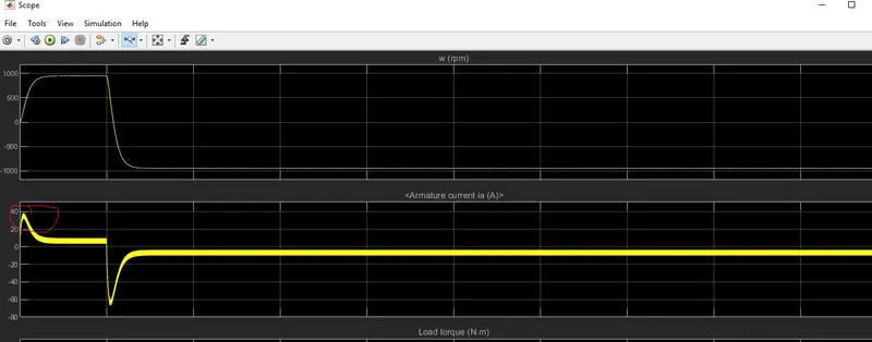
B. Comment on the armature current shoot-up from the scope results.
SOL:
We know that back emf Eb= Va-IaRa
Va = Eb+IaRa
during starting Eb=0
Va= IaRa
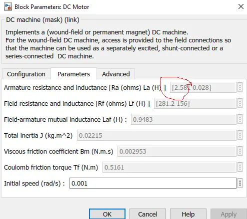
Ra=2.581 ohms
Va=172 volts @75% duty cycle
Ia= 60A amps during starting
Once the motor get started from zero speed Back emf is developed hence the Armature current is maintained low.
For the above reason only there is shoot in armature current (Ia) during starting.
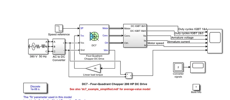
C ) Refer to the help section of ‘The Four-Quadrant Chopper DC Drive (DC7) block’. Compare it with the H-bridge model.
H-bridge model:
The Four-Quadrant Chopper DC Drive (DC7) block:
|
s.no |
H-bridge model | The Four-Quadrant Chopper DC Drive (DC7) block: |
| 1 | 240 v Dc supply from battery is used | It converts 3phase AC to DC with chopper control |
| 2 | Field winding was exited seperately | Field is directly exited itself |
| 3 | We have to change the individual setting in igbt | We can easily change the igbt setting inblock itself |
| 4 | It is a open loop control |
It is a closed loop control |
| 5 | Blocks required to model is high | Blocks required to model is low |
| 6 | It has no pi controller | it has pi controller |
| 7 | No smooth operation while starting or change in speed | Speed operation during entire process |
2) Develop a 2-quadrant chopper using simulink & explain the working of the same with the relevant results. (Refer to article - Multiquadrant operation of motor )
sol:
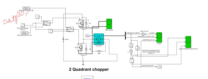
Simulation Drawing for 20 % duty cycle:
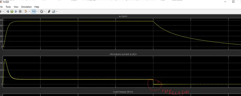
OUTPUT with 20% duty cycle:
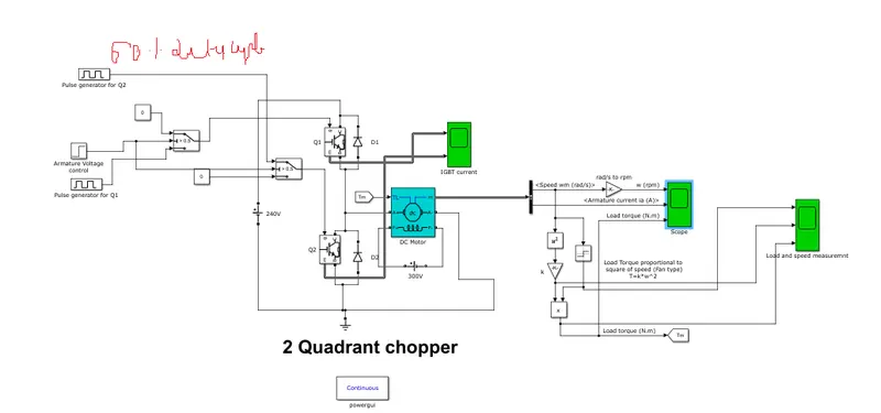
Simulation Drawing for 60 % duty cycle:
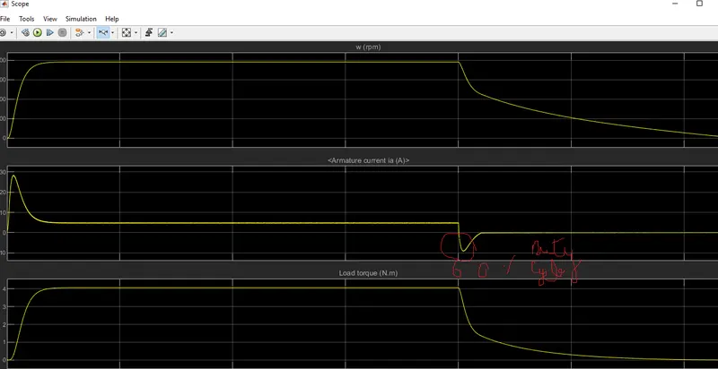
OUTPUT with 60% duty cycle:
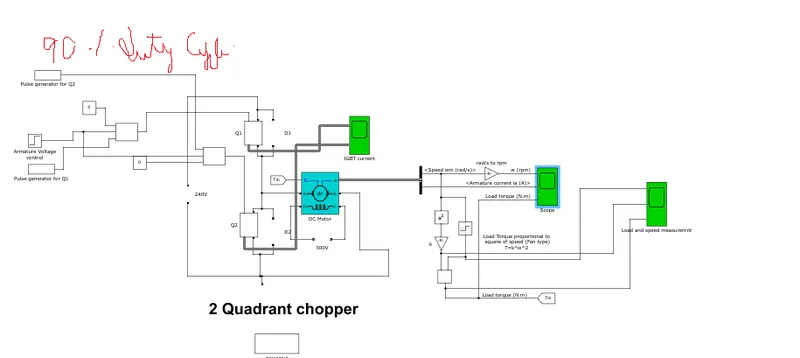
Simulation Drawing for 90 % duty cycle:
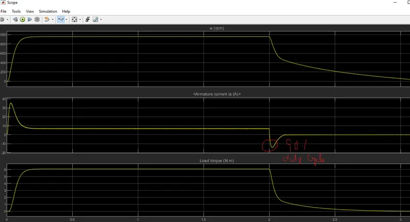
OUTPUT with 90% duty cycle:
This model consists of two IGBT's Q1 and Q2 and two diodes D1 and D2.
Q1 for motoring and Q2 for braking.
During motoring operation Q1 conducts the motor starts to run.
when Q2 is turned off the polarity in the motor is reversed so that the diode D2 starts conducts or we can use Q2 to turn on to deliever a stored volatge into source.
Iam using a fan as a load which i used in first question.
From the result i found that when Q2 is conducted:
- In 20 % duty cycle when motor is turned off the current never goes to negative direction.
- In 60 % duty cycle when motor is turned off the regen current is developed which is 10 amps.
- In 90 % duty cycle when motor is turned off the regen current is developed which is 12 amps.
3. Explain in a brief about operation of BLDC motor.
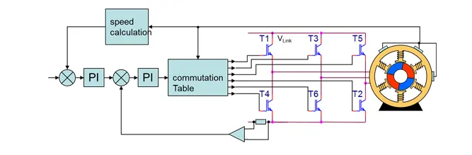
Block diagam:
Phase output:
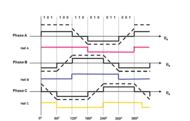
Six Step commutation sequence:
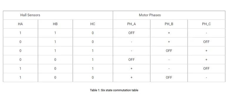
- When ever a current carrying conductor placed in a magnetic field it experiences the force on the conductor according to left hand rule(motoring principle)
- Bldc motor has stator and rotor which is same as Dc motor
- In dc motor there is field winding(stator) and armature winding (rotor)
- when the windings are exited by the current it genrates a force.
- In bldc there is only one winding which is in stator and rotor has permanent magnet
- stator have a 3phase winding which is phase shifted electrically by 120 degree
- Each phase has 2 coil sets which produces north and south electromagnet which is called as pole pairs
- For easy of explanation we are considering 2 pole pair motor
- For 3 phase connection there is a 6set of coils which is phase shifted by 60 degree
- When a Dc current flows in a particular phase it produces north pole the opposite coil produces south pole.
- In a bldc motor the motor may be connected in star or delta connection based on motor reqirement
- the three phases are U,V,W
- when we connect a DC battery supply directly to U,V phase motor doesn't start
- To start the motor we require a 3 phase inverter.
- Each phases should be conducted for 60 degree.
- By changing the pwm the voltage is changed hence the speed also changed.
- BLDC motor has two modes sinusoidal and trapesoidal.
- According the winding the motor modes are changed
- For each 120 degree the one phase as made constant and we have to change another phase
- Motor can be classified into two OUTRUNNER, INRUNNER
- In both the classification the electrical winding is in stationary part the permanant magnet will rotate
- BLDC motors are controlled by open loop or closed loop.
- IN ESC (electronic speed control) it works inopen loop back emf is used as a feedback.
- IN FOC controls it requires hall effect or encoder to detect rotor position and need a current sensor.