Week-11 Challenge: Braking
- For a defined driving cycle, calculate the energy required for braking.
Driving cycle braking energy result:
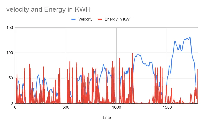
Energy During braking = (1/2)*(Mass*V*V)
Mass = 500 KG
V = velocity
V= (initial velocity - final velocity)
Driving Cycle:
| Time | Velocity | Mass(KG) |
| 0 | 0 | 500 |
| 1 | 0 | 500 |
| 2 | 0 | 500 |
| 3 | 0 | 500 |
| 4 | 0 | 500 |
| 5 | 0 | 500 |
| 6 | 0 | 500 |
| 7 | 0 | 500 |
| 8 | 0 | 500 |
| 9 | 0 | 500 |
| 10 | 0 | 500 |
| 11 | 0 | 500 |
| 12 | 0.2 | 500 |
| 13 | 1.7 | 500 |
| 14 | 5.4 | 500 |
| 15 | 9.9 | 500 |
| 16 | 13.1 | 500 |
| 17 | 16.9 | 500 |
| 18 | 21.7 | 500 |
| 19 | 26 | 500 |
| 20 | 27.5 | 500 |
| 21 | 28.1 | 500 |
| 22 | 28.3 | 500 |
| 23 | 28.8 | 500 |
| 24 | 29.1 | 500 |
| 25 | 30.8 | 500 |
| 26 | 31.9 | 500 |
| 27 | 34.1 | 500 |
| 28 | 36.6 | 500 |
| 29 | 39.1 | 500 |
| 30 | 41.3 | 500 |
| 31 | 42.5 | 500 |
| 32 | 43.3 | 500 |
| 33 | 43.9 | 500 |
| 34 | 44.4 | 500 |
| 35 | 44.5 | 500 |
| 36 | 44.2 | 500 |
| 37 | 42.7 | 500 |
| 38 | 39.9 | 500 |
| 39 | 37 | 500 |
| 40 | 34.6 | 500 |
| 41 | 32.3 | 500 |
| 42 | 29 | 500 |
| 43 | 25.1 | 500 |
| 44 | 22.2 | 500 |
| 45 | 20.9 | 500 |
| 46 | 20.4 | 500 |
| 47 | 19.5 | 500 |
| 48 | 18.4 | 500 |
| 49 | 17.8 | 500 |
| 50 | 17.8 | 500 |
| 51 | 17.4 | 500 |
| 52 | 15.7 | 500 |
| 53 | 13.1 | 500 |
| 54 | 12.1 | 500 |
RES:
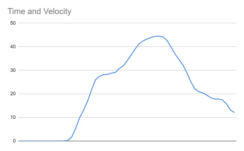
Braking Energy Calculation chart:
| Time | Velocity | Mass(KG) | Change in velocity | Energy | Energy in KWH |
| 0 | 0 | 500 | 0 | 0 | 0 |
| 1 | 0 | 500 | 0 | 0 | 0 |
| 2 | 0 | 500 | 0 | 0 | 0 |
| 3 | 0 | 500 | 0 | 0 | 0 |
| 4 | 0 | 500 | 0 | 0 | 0 |
| 5 | 0 | 500 | 0 | 0 | 0 |
| 6 | 0 | 500 | 0 | 0 | 0 |
| 7 | 0 | 500 | 0 | 0 | 0 |
| 8 | 0 | 500 | 0 | 0 | 0 |
| 9 | 0 | 500 | 0 | 0 | 0 |
| 10 | 0 | 500 | 0 | 0 | 0 |
| 11 | 0 | 500 | 0 | 0 | 0 |
| 12 | 0.2 | 500 | 0 | 0 | 0 |
| 13 | 1.7 | 500 | 0 | 0 | 0 |
| 14 | 5.4 | 500 | 0 | 0 | 0 |
| 15 | 9.9 | 500 | 0 | 0 | 0 |
| 16 | 13.1 | 500 | 0 | 0 | 0 |
| 17 | 16.9 | 500 | 0 | 0 | 0 |
| 18 | 21.7 | 500 | 0 | 0 | 0 |
| 19 | 26 | 500 | 0 | 0 | 0 |
| 20 | 27.5 | 500 | 0 | 0 | 0 |
| 21 | 28.1 | 500 | 0 | 0 | 0 |
| 22 | 28.3 | 500 | 0 | 0 | 0 |
| 23 | 28.8 | 500 | 0 | 0 | 0 |
| 24 | 29.1 | 500 | 0 | 0 | 0 |
| 25 | 30.8 | 500 | 0 | 0 | 0 |
| 26 | 31.9 | 500 | 0 | 0 | 0 |
| 27 | 34.1 | 500 | 0 | 0 | 0 |
| 28 | 36.6 | 500 | 0 | 0 | 0 |
| 29 | 39.1 | 500 | 0 | 0 | 0 |
| 30 | 41.3 | 500 | 0 | 0 | 0 |
| 31 | 42.5 | 500 | 0 | 0 | 0 |
| 32 | 43.3 | 500 | 0 | 0 | 0 |
| 33 | 43.9 | 500 | 0 | 0 | 0 |
| 34 | 44.4 | 500 | 0 | 0 | 0 |
| 35 | 44.5 | 500 | -0.1 | 2.5 | 0.025 |
| 36 | 44.2 | 500 | 0.3 | 22.5 | 0.225 |
| 37 | 42.7 | 500 | 1.5 | 562.5 | 5.625 |
| 38 | 39.9 | 500 | 2.8 | 1960 | 19.6 |
| 39 | 37 | 500 | 2.9 | 2102.5 | 21.025 |
| 40 | 34.6 | 500 | 2.4 | 1440 | 14.4 |
| 41 | 32.3 | 500 | 2.3 | 1322.5 | 13.225 |
| 42 | 29 | 500 | 3.3 | 2722.5 | 27.225 |
| 43 | 25.1 | 500 | 3.9 | 3802.5 | 38.025 |
| 44 | 22.2 | 500 | 2.9 | 2102.5 | 21.025 |
| 45 | 20.9 | 500 | 1.3 | 422.5 | 4.225 |
| 46 | 20.4 | 500 | 0.5 | 62.5 | 0.625 |
| 47 | 19.5 | 500 | 0.9 | 202.5 | 2.025 |
| 48 | 18.4 | 500 | 1.1 | 302.5 | 3.025 |
| 49 | 17.8 | 500 | 0.6 | 90 | 0.9 |
| 50 | 17.8 | 500 | 0 | 0 | 0 |
| 51 | 17.4 | 500 | 0.4 | 40 | 0.4 |
| 52 | 15.7 | 500 | 1.7 | 722.5 | 7.225 |
| 53 | 13.1 | 500 | 2.6 | 1690 | 16.9 |
| 54 | 12.1 | 500 | 1 | 250 | 2.5 |
Brakine energy:
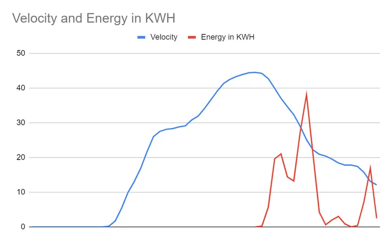
In normal engine vehicle this is achieved by friction brakes. we also take care of heat while braking.
2) Why electric motor can’t develop braking torque at high speed similar to starting? How electric and mechanical brakes are coordinated?
- Braking is a method to stop the running motor or vehicle.
- In IC vehicles the friction brakes are used to stop the vehicles.
- In EV and hev motor will act a motoring and braking.
- Motor can be operated in four qudrant.
- For simplicity iam taking forward motion reverse is same as forward.
- In forward running conditions it has two quadrants. forward motoring and forward braking.
- In forward motoring both torque and speed are positive.
- In forward braking speed is positive and torque is negative.
- let us consider DC motor is used in vehicle.
- It has two coils field coil and armature coil.
- According to flemings left hand rule when a current carrying conductor is placed in a magnetic field it experiences a force in a conductor.
- Braking has 3 types plugging, dynamic braking and regenerative braking.
- Regenertaive braking are mostly prefered it has a limitation of converter circuit and battery charging current.
- if we consider a motoring operation the torque can be controlled by speed.
- motor was operated in two modes. Constant Torque mode and constant power mode.
- motor has a critical speed limit if we exceed the limit the motor runs in constant power mode.
- in constant power mode the motor is running at very high speed.in this the torque is decreased.
- When we running a motor at high speed and take the motor to zero speed high torque is required to stop the motor.
- During high speed the excess energy cannot be dissipated as heat in motor. which will damage the winding.
- So that we have to trasfer the brake energy to the some other medium.
- Peak acceleration torque is not equal to peak decelaration torque.
How electric and mechanical brakes are coordinated?
- IN ev Two brakes are used electrical brake and mechanical brake.
- it is configured in two modes Series brake control and Parallel brake control.
- IN series brakemode one after another brake was applied
- In Parallel brake control both the brakes are applied.
- IN all the two modes this decission is taken by the main controller based on the speed inputs.
- Electric Drive Intelligent Brake - It is the efficient method of vehicle braking. They also use Mechanical brake and electric brake.
- For high deceleration both mechnaicalnad electrical brakes are used when it slows downthe Mechanical brake is cutoff and the brake was applied by electrical motor.
- In low speed braking electrical braking is a good choice in EV application.
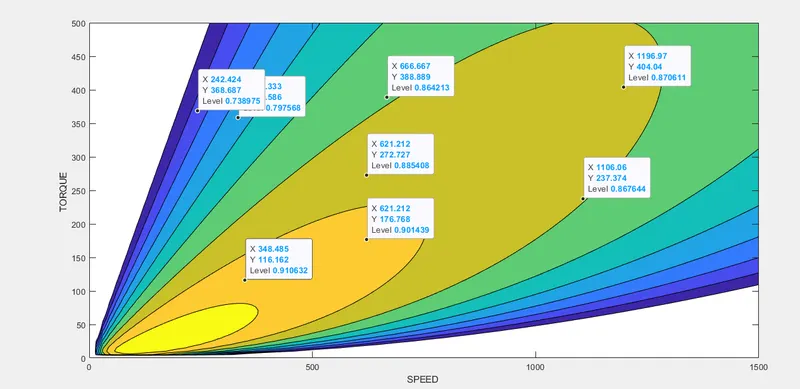
3. Make a MATLAB program which plots contour of given motor speed, torque and efficiency values. Attach the code as a .m file attach a screenshot of all the plots.
SOL:
%clear all
close all
clear all
clc
% formulas needed
%Copper loss = Kc* Torque *Torque
% Ironloss= Ki* speed
% windage loss = Kw* (speed*speed*speed0
% prepering the array
speed = linspace(0,1500);
torque = linspace(0,500);
% LOSS COEFFICIENTS
%kc = 0.23; % COPPER LOSSES
%ki = 0.008; % IRON LOSSES
%kw = 0.000020; % WINDAGE LOSSES
% C= constant loss
% kc,ki, kw, Care some coonstant value this will be given by motor
% manufacturers
% efficiency = output power / input power
% input power = copperloss+ iron loss+ windage loss+ constant
% loss+outputpower
% output power= 2*3.14*speed*torque/60
[X,Y] = meshgrid(speed,torque);
copper_loss = (Y.^2)*kc;
iron_loss = X*ki;
windage_loss = (X.^3)*kw;
K = 20; % constant loss
output_power = X.*Y;
input_power = (copper_loss)+(iron_loss)+(windage_loss)+(output_power)+K;
Efficiency = (output_power)./(input_power);
n = linspace(0.7,0.95,10); % run time
contourf(X,Y,Efficiency,n);
ylabel('TORQUE ')
xlabel('SPEED ')
RES: