Week-7 Challenge: DC Motor Control
Q.
(1).Ans:-
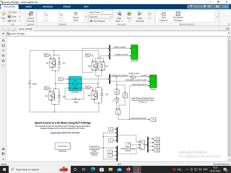
(A).MATLAB demo model named ‘Speed control of a DC motor using BJT H-bridge':-
* The BJT (Bipolar Junction Transistor ) operates as an IGBT , when used for power switching applications.
* When it is conducting BJT operating in the saturated region, a forward voltage Vf is developed between collector and emitter in the range of 1 V.
* Then the IGBT block can be used to model the BJT device.
* The armature mean voltage can be varied from 0 to 240 V when the duty cycle Pulse Generator is varied from 0 to 100%, these change in pulse generator block.
* The H-bridge consists of four BJT or Diode pairs these BJT simulated by IGBT models.
* Two transistors are switched simultaneously Q1 and Q4 or Q2 and Q3.
* When Q1 and Q4 are fired, a positive voltage is applied to the motor and diodes D2-D3 operate as free-wheeling diodes when Q1 and Q4 are switched off.
* In this cycle of operation the motor rotates in forward direction.
* When Q2 and Q3 are fired, a negative voltage is applied to the motor and diodes D1-D4 operate as free-wheeling diodes when Q2 and Q3 are switched off.
* In this cycle of operation the motor rotates in reverse direction.
Speed control of a DC motor using BJT H-bridge:-
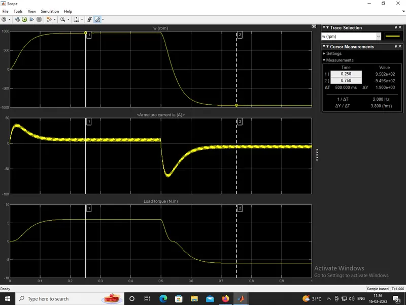
Output results:-
(1).Ans:-
(B).Armature current shoot-up from the scope results:-
* In this, matlab demo model was runned and performed a different results.
* By keeping all the parameters default and only changes the duty cycle that was change in the pulse generatorblock.
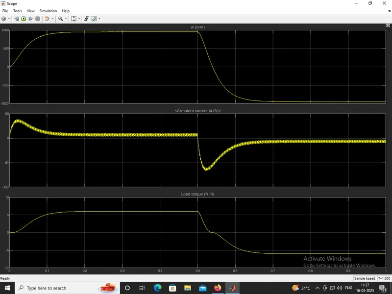
* Pulse width (duty cycle) in different stages is 75%, 55%, and 40%.
Pulse width 75%:-
Pulse width 55%:-
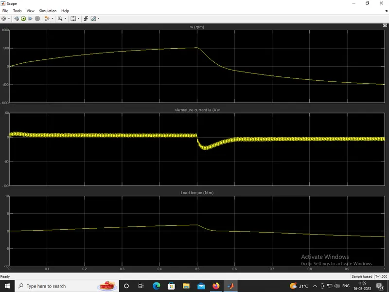
Pulse width 40%:-
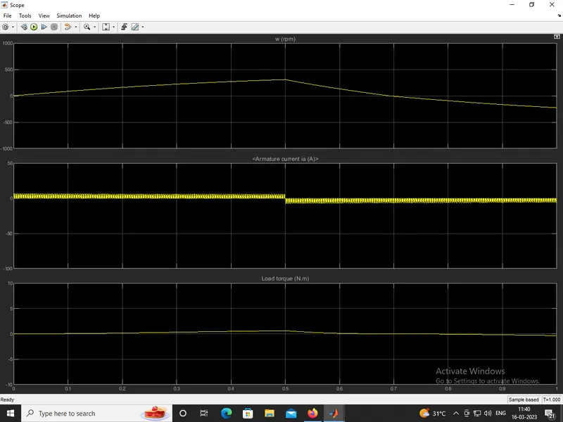
Comments:-
* In the above three different pulse width (duty cycles) we observe that:-
* For duty cycle 75%, the plot of the the current has initially very high value and then becomes steady and after that shows same path in the negative direction.
* For duty cycle 40%, the plot of the the current has very low value and steady state i.e when compared to three different duty cycles it was decreasing.
* From these three comparision we observe that by decreasing the pulse width (duty cycle) we get the steady and smoother current flow in the motor.
* The shoot up happens because of the switching in the circuit that cause heat losses during switching.
* To avoid these losses, we use heat sink material to dissipate the heat, from this the motor can change its direction of rotation easily and very smoothly.
(1).Ans:-
(C).The Four-Quadrant Chopper DC Drive (DC7) block:-
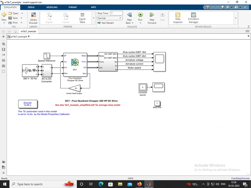
Output results:-
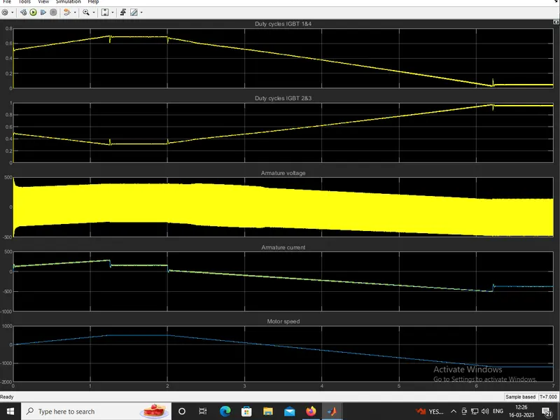
Comparision The Four-Quadrant Chopper DC Drive (DC7) block with the H-bridge model:-
* Chopper is a DC-DC converter circuit, it will convert a fixed DC into variable DC.
* The 200 HP DC motor is separately excited with a constant 150 V DC field voltage source.
* The converter is fed by a 515 V DC bus obtained by rectification of a 380 V AC 50 Hz voltage source.
* In order to limit the DC bus voltage during dynamic braking mode, a braking chopper has been added between the diode rectifier and the DC7 block.
* The first regulator is a speed regulator, followed by a current regulator.
* The speed regulator outputs the armature current reference (in p.u.) used by the current controller in order to obtain the electromagnetic torque needed to reach the desired speed.
* H-bridge is a simple circuit by that you control a DC motor to go backward or forward direction.
* If you close switch 1 and 4, you have plus connected to the left side of the motor and minus to the other side. And the motor will start spinning in one direction.
* If you instead close switch 2 and 3, you have plus connected to the right side and minus to the left side. And the motor spins in the opposite direction.
(2).Ans:-
Two-quadrant chopper using simulink & working of the same with the relevant results:-
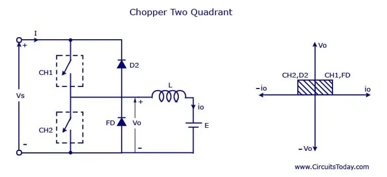
Simulink model:-
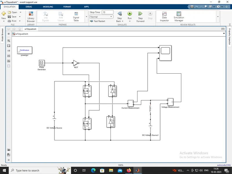
Blocks used for two-quadrant chopper in simulink are:
* PowerGUI
* Pulse generator
* Voltage Measurement
* Current Measurement
* Series RLC Branch with only inductor
* DC Voltage Source
* NOT Operator
* Mosfet
* Diode
* Scope
Working:-
* Two quadrant chopper is also called as type c chopper.
* Type c chopper is obtained by connecting type A and type B choppers in parallel.
* We will always get a positive output voltage V0 as the freewheeling diode FD is present across the load.
* When the chopper is on the freewheeling diode starts conducting and the output voltage Vo will be equal to Vs .
* The direction of the load current Io will be reversed. The current Io will be flowing towards the source and it will be positive regardless the chopper is on or the FD conducts.
* The load current will be negative if the chopper is or the diode D2 conducts. We can say the chopper and FD operate together as type A chopper in first quadrant.
* In the second quadrant, the chopper and D2 will operate together as type B chopper.
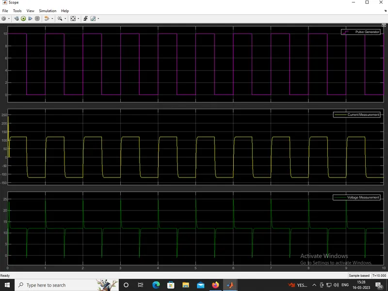
Setting the parameters:-
In the pulse generator
* amplitude = 1
* time period = 1.0sec
* pulse width = 50%
* phase sequence = 0
D.c voltage source 1:
* amplitude = 24
D.c voltage source 2:
* amplitude = 12
Output results:-
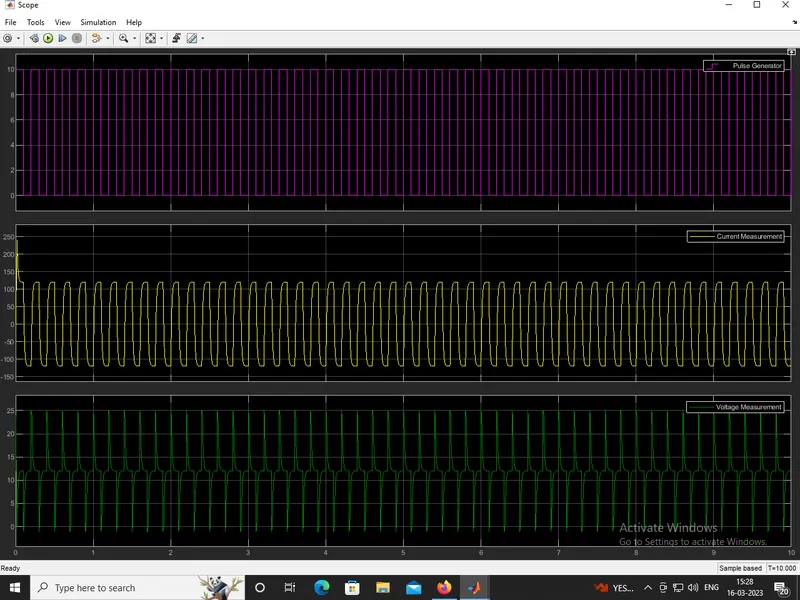
Changing the parameters:-
In the pulse generator
* amplitude = 1
* time period = 0.2sec
* pulse width = 50%
* phase sequence = 0
D.c voltage source 1:
* amplitude = 24
D.c voltage source 2:
* amplitude = 12
Output results:-
Comments:-
* W observe from the result, we can see that voltage is never going to 0 and always lying on positive side of the axis
* Current is increasing and decreasing and also lying in both positive and negative axes.
* These are the observations of a 2-quadrant chopper simulink model performed in the different parameters of a pulse generator.
(3).Ans:-
OPERATION OF BRUSH LESS DC MOTOR:-
CONSTRUCTION:
* A commutator-brushes arrangement helps in achieving unidirectional torque in a typical dc motor.
* Obviously, commutator and brush arrangement is eliminated in a brushless dc motor.
* Here, an integrated inverter/switching circuit is used to achieve unidirectional torque.
* That is why these motors are, sometimes, also referred as 'electronically commutated motors.
* BLDC motor also consists of two main parts a stator and a rotor. Permanent magnets are mounted on the rotor of a BLDC motor, and the stator is wound for a specific number of poles.
* Also, a control circuit is connected to the stator winding.
* This is the basic constructional difference between a brushless motor and a typical dc motor.
TYPES OF BLDC MOTORS:-
(i).Inner rotor design:-
* This is a conventional design, where the rotor is located at the core (center) and stator winding surrounds it.
(ii).Outer rotor design:-
* In this configuration, the rotor is external. i.e. stator windings are located at the core while the rotor, carrying permanent magnets, surrounds the stator.
WORKING OF BLDC MOTORS:-
* When the poles of a motor was same to eachother it was rippled and completed 180degrees turn of direction.
* When the poles was opposite to eachother is was stopped rotating so,here to run the motor we connect motor signes reverse,it is not possible to do like this.
* So, hall effect sensor was used in the brushless dc motor operation.
* Stator windings of a BLDC motor are connected to a control circuit (an integrated switching circuit or inverter circuit).
* The control circuit energizes proper winding at the proper time, in a pattern which rotates around the stator.
* Permanent magnets on the rotor try to align with the energized electromagnets of the stator, and as soon as it aligns, the next electromagnets are energized.
* Brushes require frequent replacement due to mechanical wear, hence, a brushed DC motor requires periodic maintenance.
* Also, as brushes transfer current to the commutator, sparking occurs.
* Brushes limit the maximum speed and the number of poles the armature can have.
* These all drawbacks are removed in a brushless DC motor. An electronic control circuit is required in a brushless DC motor for switching stator magnets to keep the motor running.
* This makes a BLDC motor potentially less rugged.
* Advantages of BLDC motor over brushed motors are increased efficiency, reliability, longer lifetime, no sparking and less noise, more torque per weight, etc.
APPLICATIONS OF BLDC MOTORS:-
* BLDC motors fulfill many requirements that a brushed DC motor does.
* But as they require a complicated control circuit and due to cost considerations, they haven’t yet completely replaced brushed DC motors, especially in low-cost applications.
* There are many applications where BLDC motors dominate.
* Electric Vehicles – many electric vehicles including electric and hybrid cars, electric bikes use BLDC motors.
* Modern appliances where quiet operation is desired – such as washing machines, air conditioners, etc.
* These are the construction and working principle of brussless d.c motor along with the applications was presented.