Final Project: Design of an Electric Vehicle
Q.
(1).Ans:-
To create a MATLAB model of electric car which uses a battery and a DC motor:-
Objectives:-
* To prepare a technical report about the EV model includin:
1. System level configurations
2. Model parameters
3. Results
4. Conclusion
Electrical Vehicle:-
* An electric vehicle (EV) is a vehicle that uses one or more electric motors for propulsion.
* It can be powered by a collector system, with electricity from extravehicular sources, or it can be powered autonomously by a battery.
* EVs include, but are not limited to, road and rail vehicles, surface and underwater vessels, electric aircraft , and electric spacecraft.
* For road vehicles, together with other emerging automotive technologies such as autonomous driving, connected vehicles, and shared mobility, EVs form a future mobility vision called Connected.
* EVs first came into existence in the late 19th century, when electricity was among the preferred methods for motor vehicle propulsion, providing a level of comfort and ease of operation.
* That could not be achieved by the gasoline cars of the time. Internal combustion engines were the dominant propulsion method for cars and trucks for about 100 years.
* But electric power remained commonplace in other vehicle types, such as trains and smaller vehicles of all types.
* Most electric vehicles use lithium-ion batteries (Li-Ions or LIBs). Lithium ion batteries have higher energy density, longer life span and higher power density than most other practical batteries.
* Complicating factors include safety, durability, thermal breakdown, its environmental impact and cost.
* Li-ion batteries should be used within safe temperature and voltage ranges in order to operate safely and efficiently.
* The prices of lithium-ion batteries are constantly decreasing, contributing to a reduction in price for electric vehicles.
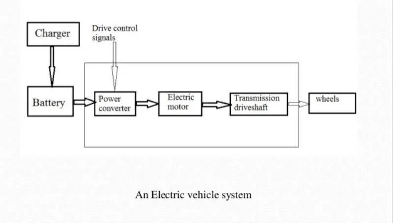
Block diagram of electrical vehicle:-
Battery:-
* The battery of an electric car can be charged through the use of ordinary grid electricity at a specialized power station.
* But aside from the conventional lithium-ion battery technologies, there are also other major battery technologies which can be used for electric cars.
(i).Lithium-ion battery:-
* A Lithium-ion (Li-ion) battery is a type of rechargeable battery used in electric vehicles and a number of portable electronics.
* They have a higher energy density than typical lead-acid or nickel-cadmium rechargeable batteries.
(ii).Lead-acid batteries:-
* Lead-acid batteries are only currently being used in electric vehicles to supplement other battery loads.
* These batteries are high-powered, inexpensive, safe, and reliable, but their short calendar life and poor cold-temperature performance make them difficult to use in electric vehicles.
Power converters:-
* An inverter is a device that converts DC power from the battery to AC power in an electric vehicle motor.
* The inverter can change the speed at which the motor rotates by adjusting the frequency of the alternating current.
Electric motor:-
* The Brushless DC Electric Motor (BDCM)
* These motors are often considered a suitable option for high-performance electric vehicles.
* That's primarily because they are known to offer increased efficiency, reliability, and power output.
* Choosing an electric motor depends on the car’s system voltage.
* They can be structured to use either AC or DC current.
* AC motors are less expensive and lighter compared to DC motors.
PROCEDURE :
(i).Tires:-
* To provide this necessary grip, EV tires are designed with specific stiff and wide center rib patterns to reduce potential slippage and abnormal abrasions.
* In addition to interlocking grooves in the tread pattern to prevent hydroplaning and compensate for the increase in torque.
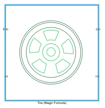
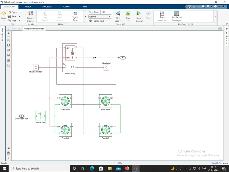
* The 'N' port of the tire corresponds to the Normal Reaction acting on it.
* The 'A' port corresponds to the Mechanical Rotational conserving port for the wheel axle.
* The both wheels on the same axle should form a connection through their respective A ports.
* Connection 'H' corresponds to the Mechanical Translational conserving port for the wheel hub through which the thrust developed by the tire is applied to the vehicle.
* There, all the 4 wheels form a connection through their respective H ports and this is in turn connected to the translational hub of the vehicle body.
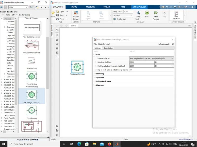
* The connection 'S' represents the output port for slip of the tire.
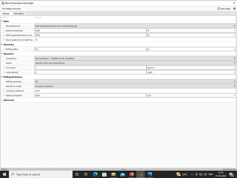
* The tire radius is given as 0.3 m.
* The tire inertia is kept as 1 kg-m^2.
* And, the rolling resistance is given with a constant coefficient of 0.015.
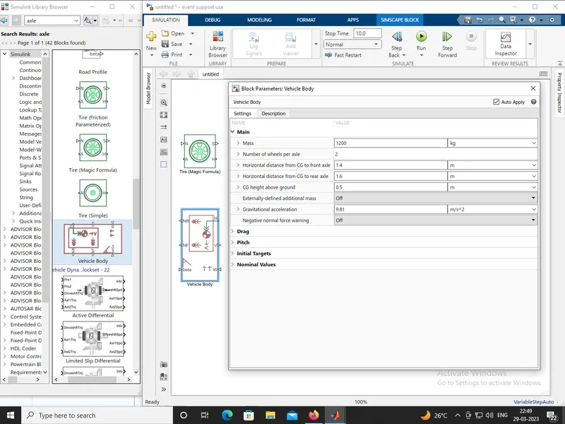
The complete subsystem is shown below:-
Vehicle body subsystem:
(ii).DC Motor:-
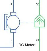
* DC motors are classified into three categories namely brushed DC motor, BLDC or brushless DC motor, and stepper.
* Brushed DC motors are widely used in electric vehicles for retracting, positioning and extending electrically-powered side windows.
* These motors are suitable for many uses because of their low.
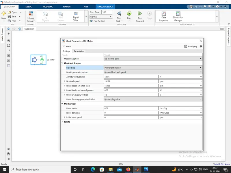
* The connection 'R' represents the Rotor (rotational output) while the connection 'C' is for the Casing (stationary).
* Where, the 'R' port is connected to the input of the vehicle subsystem created earlier.
* The 'C' port is connected to a mechanical rotational reference.
(iii).Motor Controller:-
H-Bridge circuit:
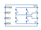
* A H-bridge is an electronic circuit that switches the polarity of a voltage applied to a load.
* These circuits are often used in robotics and other applications to allow DC motors to run forwards or backwards.
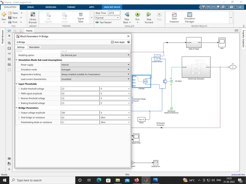
* In Averaged mode, the 'PWM' port voltage divided by the PWM signal amplitude parameter defines the ratio of the on-time to the PWM period.
* Connection 'REF' is for the reference input. This combined with the PWM connected will form the pulse input for the H-Bridge.
* Here, the REF input is connected to the Electrical Reference (ground).
* Connection 'REV' corresponds to the reverse motion of the motor which essentially means, the backward motion of the vehicle.
* Here, the backward motion of the vehicle is not accounted for and so, the port is connected to the electrical reference.
* Connection 'BRK' is for the braking of the vehicle.
* Simulink provides an inbuilt Controlled PWM Voltage block.
* This block is used for providing the proper pulse inputs to the H-Brdige circuit.
Controlled pwm voltage:-
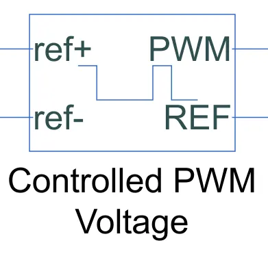
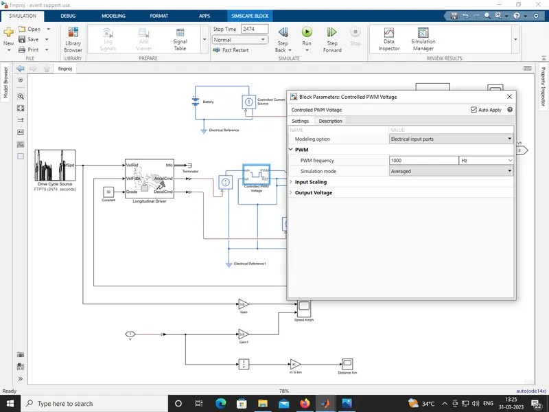
* The PWM & REF connections are for the corresponding ports on the H-Bridge circuit.
*The 2 reference inputs correspond to the throttle inputs given by the driver.
* The block generates corresponding pulse width as per the accelerations and brakes apllied by the driver himself.
* The PWM frequency is 1000 Hz. Also, the simulation mode is Averaged as that in the H-Bridge circuit.
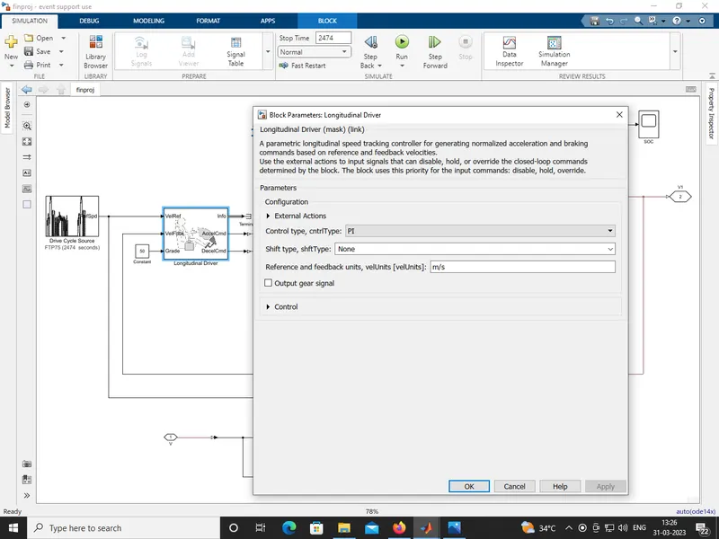
(iv).Longitudinal Driver:-
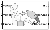
* The VelRef port is the reference velocity port where the input drive cycle data is fed.
* The VelFdbk port corresponds to the feedback velocity.
* The actual velocity output given by the vehicle body is connected here.
* Grade corresponds to the grade angle. For this simulation, no inclination is considered and hence, a constant block with value 0 is connected.
* Info gives the output for the bus signal for different block calculations like difference in reference vehicle speed and vehicle speed, etc.
* AccelCmd & DecelCmd correspond to the acceleration and deceleration commands generated respectively.
* And are connected to the corresponding ports of the Controlled PWM Voltage block.
(v).Battery Pack:-
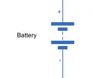
* Energy storage systems, usually batteries, are essential for all-electric vehicles, plug-in hybrid electric vehicles (PHEVs), and hybrid electric vehicles (HEVs).
* Lithium-ion batteries are currently used in most portable consumer electronics such as cell phones and laptops because of their high energy per unit mass relative to other electrical energy storage systems.
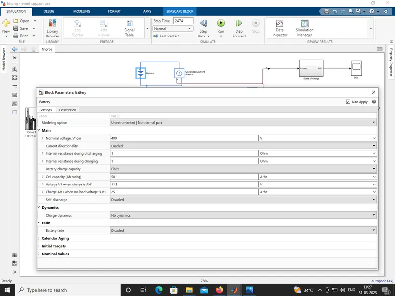
* To model the Battery pak, a simple Battery block is used. This is because, if the generic battery block is used instead, the simulation will run for a much longer time.
* Here, the selected option for Battery Charge Capacity is Finite.
* Accordingly, the block models the battery as a series internal resistance plus a charge-dependent voltage source.
* The Battery Nominal Voltage is given as 400V.
* The Ampere-hour rating is assumed to be 50.
* The rest all paramaters are left with their default values.
(vi).Reference Velocity (Drive Cycle):-
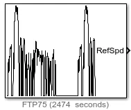
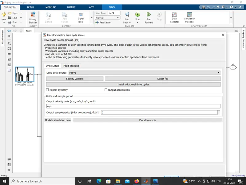
* The Drive Cycle Source block is used to provide the reference speed for the simulation.
* It generates a standard or user-specified longitudinal drive cycle.
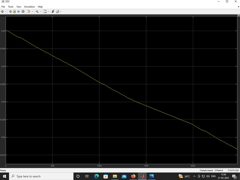
(vii).Battery State of Charge (SOC):-
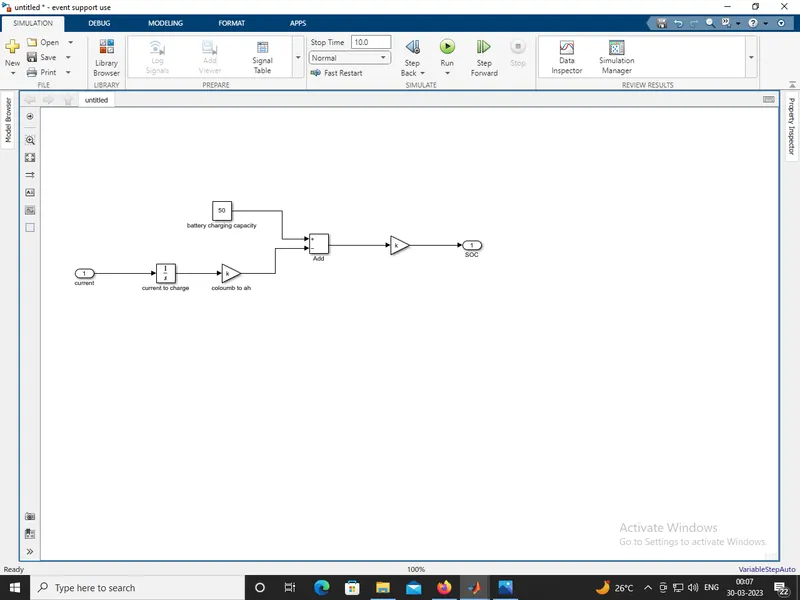
* The essential process to calculate the SOC is by subtracting the charge from the rated capacity of the battery.
* Accordingly, the current is integrated w.r.t. time to get the charge in coulumbs. Now this coulumb value is modified into Ampere hours.
* This value is now subtracted from the charging capacity of the battery i.e. 50 Ah.
Simulink model:-
Simulation:-
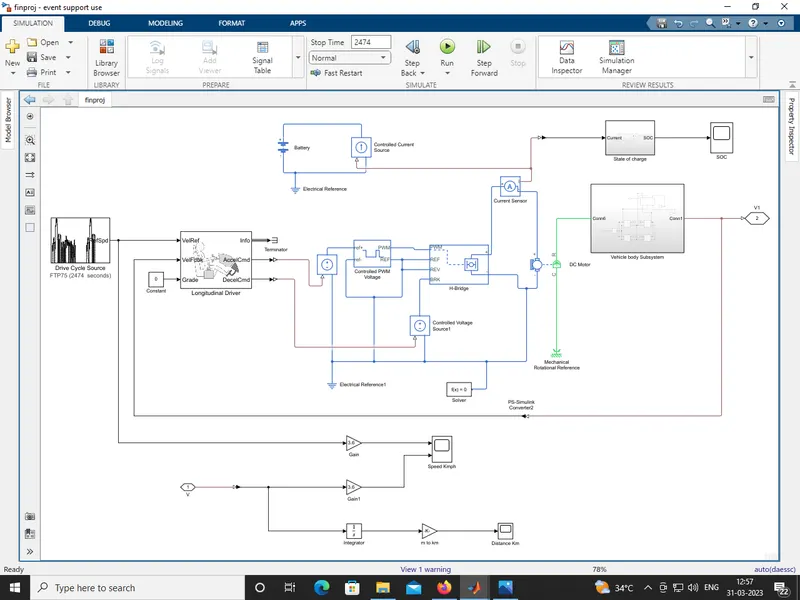
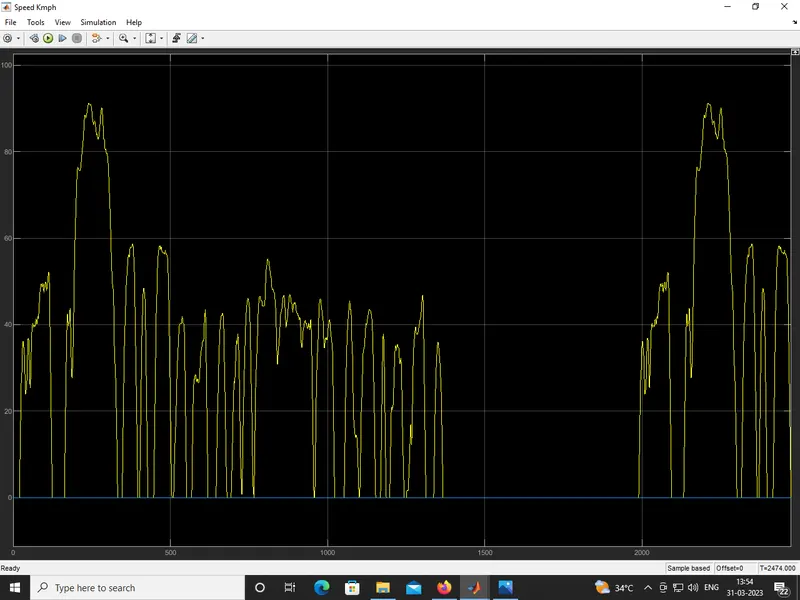
* The simulink model is run for 2474seconds and results was produced.
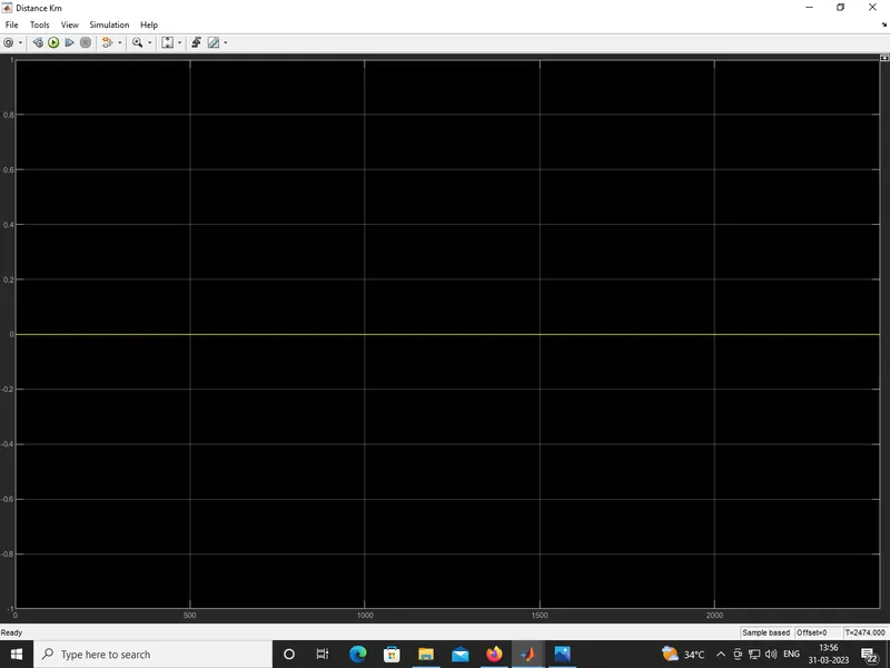
* The distance is calculated by simply time-integration of the vehicle velocity.
* Scopes are connected to analyze different outputs such as the SOC of the battery.
* The reference velocity & the actual velocity of the vehicle and the distance covered by the vehicle during the total run.
* The simple Gain blocks are used to ,there velocities are first converted from m/s to kmph values.
Output results:-
Speed kmph:
Distance in km:
Battery state of charge (SOC):
Conclusion:-
* The simulink model for design of an electric vehicle was succesfully completed.
* By using of system level configurations and parameters model was created.
* Results of the model was provided by the help of scope block.