Week-7 Challenge: DC Motor Control
Solution:
Q.No. 1A:
Speed Contraol of a DC Motor using BJT H - Bridge:
- H-Bridge consits of 4 switching element with load at the center in an H-like configuration. The speed of the DC motor can be controlled by using BJT in H-Bridge configuration.
- The below figure shows the simulink demo model of an H-bridge used to generate a chopped voltage and to control the speed of a DC motor.
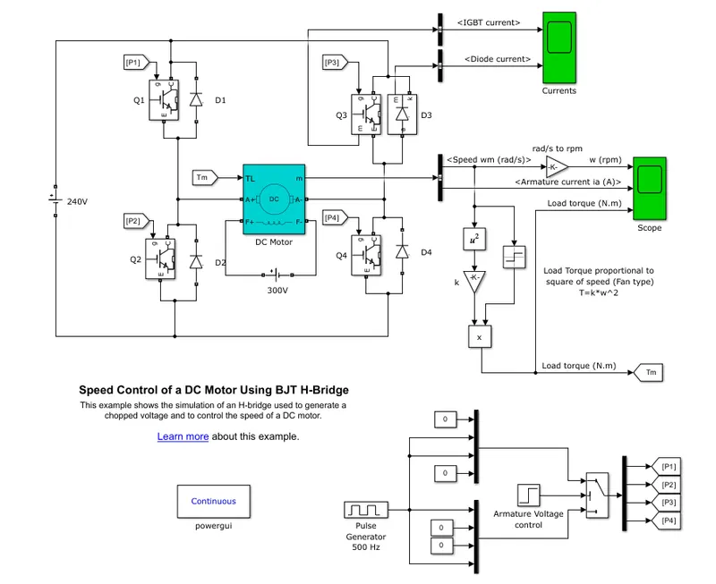
- When a Bipolar Junction Transistor (BJT) is used for power swithching application it operates as an IGBT. BJT operates in satuaration egion when it is conducting, hence a forward voltage Vf is developed between collector and emitter (approx. 1V). Therefore IGBT block can be used to model the BJT device.
Block Diagram:
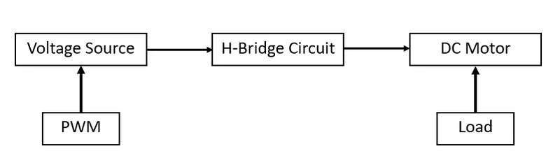
- The demo model consists of a DC voltage source, PWM block to control the input voltage to armature winding, IGBT, Diode, DC motor block, torque calculation block and scope to plot the values of current, voltage, speed, torque.
- Pulse generator of 500 hz generates the control signals for the switching device (BJT)
- DC motor with the preset values whose speed is to be controlled is connected across the supply.
- When Q1 and Q4 are ON, Positive voltage is aaplied to the motor and the current flows from Q1 to Motor to Q4, hence the motor rotates in the forward direction.
- When Q2 and Q3 are ON, Negative voltage is applied to the motor and the current flows from Q3 to Motor to Q2, hence the motor rotates in the reverse direction.
- Diodes D2 and D3 act as a freewheeling diodes at the moment when Q1 and Q4 are turned OFF and D1 and D4 acts as freewheeling diodes at the moment when Q2 and Q3 are turned Off.
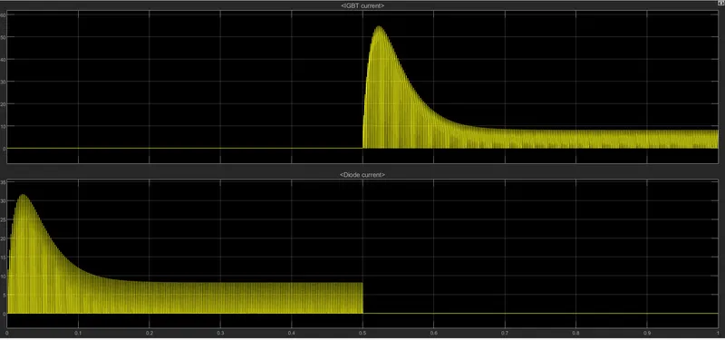
- The IGBT current and the diode currents are plotted in the scope.
- Torque is calculated in the Matlab Model and is plotted along with armature current and speed.
Q.No. 1B:
- The demo model for Speed Control of a DC Motor Using BJT H-Bridge is simulated for the preset vales of all parameter.
- Below is the graph od diode current and BJT current (Q3, D3).
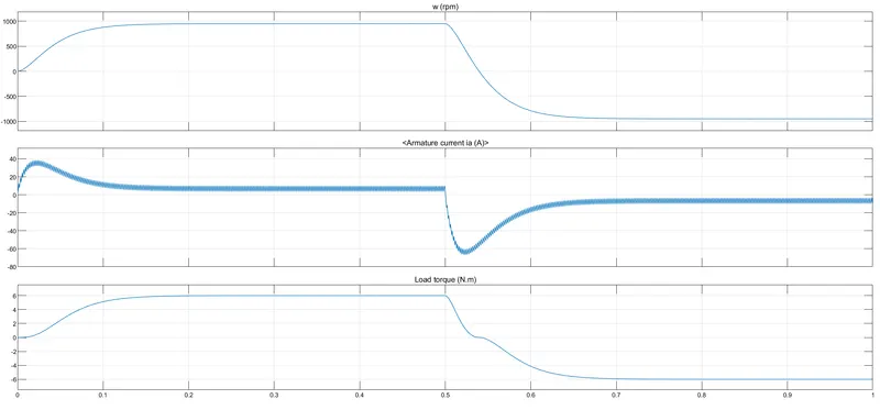
- Below is the graph of Speed, armatue current and Load torque.
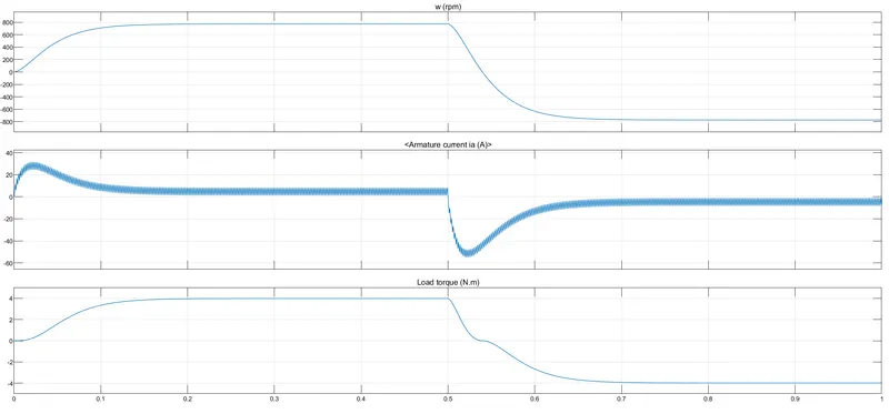
- The preset value of duty cycle of PWM unit is 70% and time period is 0.002 sec, which means the voltage is applied for longer duration (i.e, T(on)=0.0014 sec and T(off)=0.0006 sec)
- This increases the average voltage appearing accross the motor terminal (both in forward and reverse direction)
Back EMF, Eb = V-IaRa
Ia = (V-Eb)/Ra
- At the moment of switching forward to reverse direction change or reverse to forward direction change, the value of (V-Eb) will be high and therefore the armature current shoots up whenever the switching occurs.
- In order to control (reduce) the armature current shoot up, the duty cycle of the pulse generator should be reduced.
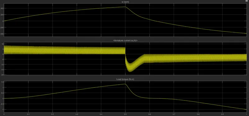
- The scope results for duty cycle = 50%, there is overshoot in the armature current when operating in reverse direction. This is because the back emf generated in the previous cycle and the terminal voltage adds up during switching.
- The scope results for duty cycle = 25%, there is no overshoot in armature current in both forward and reverse direction.
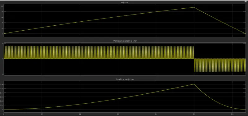
- Hence it is important to select the duty cycle such that there is nor overshoot in armature cureent and the speed of the DC motor is controlled.
Q.No. 1C:
Four - Quadrant Chopper DC Drive (DC7)
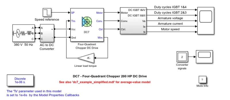
- The above figre shows the block of DC7 - Four - Quadrant Chopper DC drive used for the speed control of DC Motor.
- It consists of AC voltage source, AC to DC converter, DC7 block, selector block to calculate armature voltage, current, motor speed and duty cycle os IGBT's, Scope
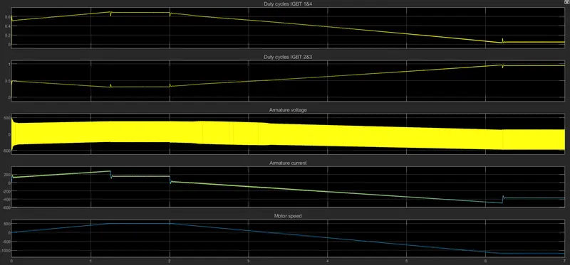
- The DC motor is separately excited with 150V DC field voltage source. The voltage to the armature is provided by IGBT converter controlled by two PI regulators.
- The 380V 50Hz AC Voltage is rectified to obtain 515V DC bus voltage which is fed into the IGBT converter. To limit the DC bus voltage during dynamic braking mode, a braking chopper has been added between the diode rectifier and the DC7 block.
- The output of speed regulator (armature current reference in pu) is fed into current controller to obtain the electromagnetic torque which is needed to reach the desired speed.
- In order to avoid sudden change in reference current that causes armatre over current and system destabilisation, the rate of change of speed reference follows the acceleration and deceleration ramps
- The current regulator controls the armature current by computing the appropriate duty ratios of the 5 kHz pulses of the four IGBT devices (Pulse Width Modulation). For proper system behaviour, the instantaneous pulse values of IGBT devices 1 and 4 are opposite to those of IGBT devices 2 and 3. This generates the average armature voltage needed to obtain the desired armature current.
- In order to limit the amplitude of the current oscillations, a smoothing inductance is placed in series with the armature circuit.
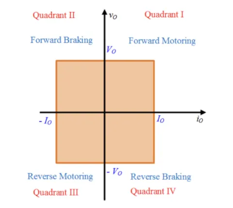
- 4 quadrant operation of chopper:
- 1st Quadrant - Forward motoring
- 2nd Quadrant - Reverse braking
- 3rd Quadrant - Reverse motoring
- 4th Quadrant - Forward braking
Comparison:
| 4 Quadrant Chopper DC drive DC7 | H - Bridge model |
| It can operate in all 4 quadrant/mode; Forward motoring, Forward braking, Reverse motoring, Reverse braking | It can operate in only two quadrants/modes; Forward motoring, Reverse motoring |
| Regenerative braking is posible in four quadrant chopper | Regenerative braking is not posible in H-Bridge model |
| Two PI regulators (speed regulator and current regulator)is used to obtain the electromagnetic torque required to reach the desired speed | No PI regulators are used in H-bridge model |
| It is a electronic switch that is used to interupt one signal under the control of another | It is a electronic circuit that switches the polarity of voltage applied to the load |
| It gives better efficiency and high power storage | The efficiency and power storage is comparitively less |
| The torque and power output range is broder | The torque and power output range is narrower |
| Maximum of 400 V can be obtained and it has chopped current values | Maximum achievale voltage is 350 and it has continuous current values |
| Widely used in automobiles | Widely used in robotics |
Result Screenshot:
4 Quadrant Chopper DC drive DC7
H-Bridge model:
Q.No. 2:
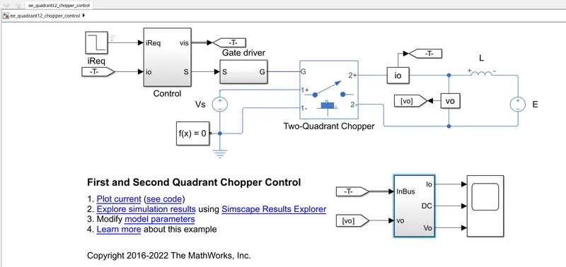
Two Quadrant operation of Chopper:
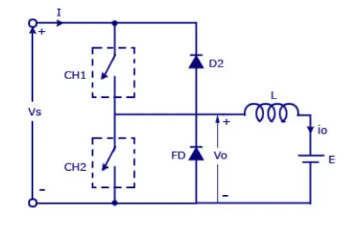
- The above figure shows the circuit diagram of 2 quadrant chopper, it consist of 2 swith CH1 and CH2 which is connected accross teh supply voltage. The 2 switches should not be turned on simultaneously,as it may cause a short circuit in supply lines. It also consits of freewhwwling diodes, inductor.
- In this type of Chopper, the average voltage will be always positive but the average load current might be positive or negative. For regenerative braking and motoring these type of chopper configuration is used.
- When the chopper CH1 is on the current flows from source to load. The inductor stores energy. When Ch1 turn OFF the freewheeling diode starts conducting and the output voltage v0 will be equal to Vs. The direction of the load current i0 will be reversed. The current i0 will be flowing towards the source.
- The load current will be negative when the CH2 is on. The current completes its path through diode D2.
- The output voltage V0 will always be positive as the freewheeling diode FD is present across the load.
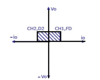
- In the 1st quadrant - both voltage and current are positive and switch CH1 and the diode FD will be conducting
- In the second quadrant - Voltage is positive by the current is negative and switch CH2 and D2 will be conducting
The simulink model for 2 quadrant model is opened (ee_quadrant12_chopper_control) and the simulation is run for the preset values
The scope shows the graph of output current (reference and actual), duty cycle and output voltage
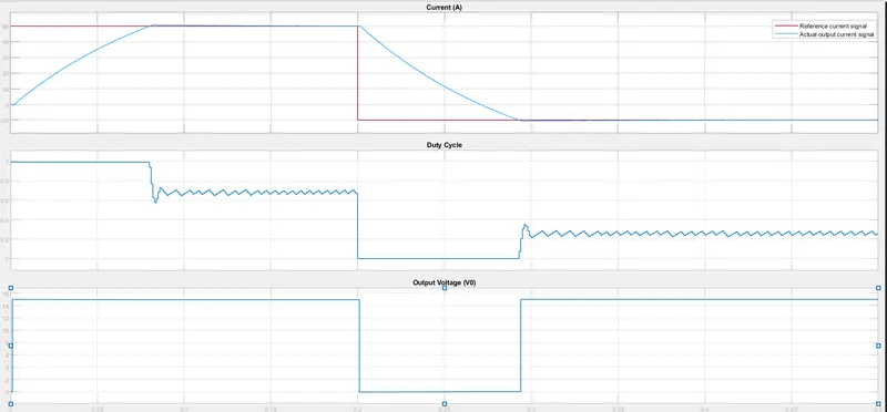
The current value is both positive and negative, but the voltage is always positive. As there is a inductor connected across the load, the actual output current gradually increases during the motoring operation and gradually decreases during the regenrative braking. Whereas there is sudden raise or fall in the reference output current during the switching.
Q.No. 3:
BLDC Motor:
Construction:
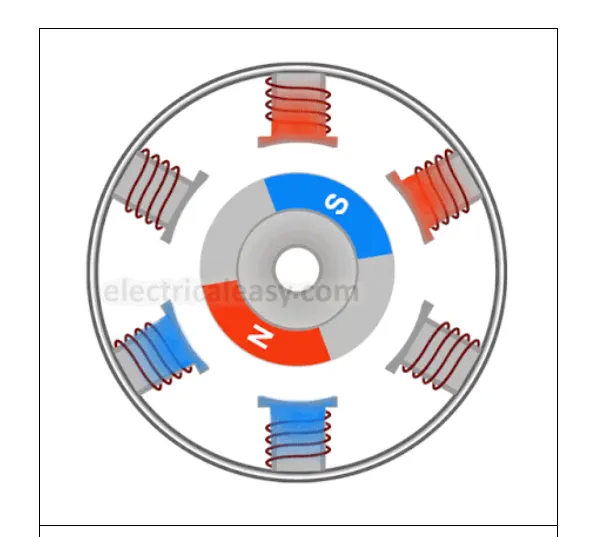
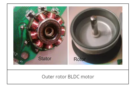
BLDC motor consist of stator and rotor. Permanent magnets are mounted on the rotor hence they are also called PMDC motor. Field windings are mounted on the stator. There are two types of BLDC motor,
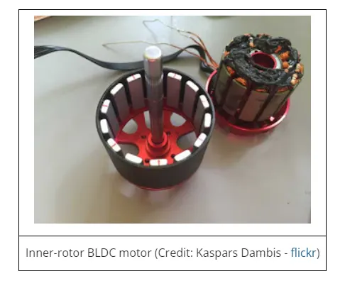
1. Inner Rotor design (inrunner) - rotor is located at the core and stator winding surrounds it
2. Outer Rotor design (outrunner) - stator windings are located at the core and the rotor, carrying permanent magnets, surrounds the stator
Operation:
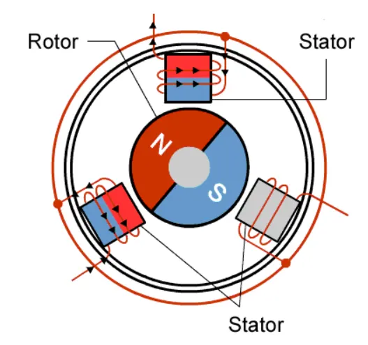
Stator windings of a BLDC motor are connected to a control circuit (an integrated switching circuit or inverter circuit). The control circuit energizes proper winding at the proper time, in a pattern which rotates around the stator. Permanent magnets on the rotor try to align with the energized electromagnets of the stator, and as soon as it aligns, the next electromagnets are energized. Thus, the rotor keeps running. The speed of the motor can be changed by changing the supply voltage to the coils.