Week-7 Challenge: DC Motor Control
1. A. Explain a MATLAB demo model named ‘Speed control of a DC motor using BJT H-bridge’.
Speed control of a DC motor using BJT H-bridge
- The H-bridge is a circuit which is used to control a DC motor in forward and backward directions
- it contains four switching elements, and the load is situated at the centre in the form of the letter 'H' as follows;
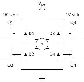
- The switching elements are usually bipolar FET transistors, in some high-voltage applications IGBTs
- The diodes are called catch diodes and are usually of Schottky type
- The top end of the bridge is connected to a power supply (battery for example) and the bottom end is grounded
- All four can be operated independently
Static Operation
|
|
|
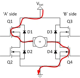
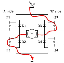
The following is the model called 'Speed control of a DC motor using BJT H-bridge' used to generate chopped voltage and to control the speed of a DC Motor.
- 'power_Hbridge' this command is used to load the model in the Simulink window
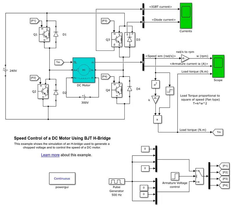
- The Bipolar Junction Transistor (BJT) operates as an IGBT when used for power-switching applications,
- When it is conducting (BJT operating in the saturated region), a forward voltage Vf is developed between the collector and emitter (in the range of 1 V). Therefore, the IGBT block can be used to model the BJT device.
- The IGBT block does not simulate the gate current controlling the BJT or IGBT. The switch is controlled by a Simulink signal (1/0).
- The DC motor uses the preset model (5 HP 24V 1750 rpm). It simulates a fan-type load (where Load torque is proportional to the square of speed). The armature mean voltage can be varied from 0 to 240 V when the duty cycle (specified in the Pulse Generator block) is varied from 0 to 100%.
- The H-bridge consists of four BJT/Diode pairs (BJT simulated by IGBT models)
- Two transistors are switched simultaneously: Q1 and Q4 or Q2 and Q3. When Q1 and Q4 are fired, a positive voltage is applied to the motor and diodes D2-D3 operate as free-wheeling diodes when Q1 and Q4 are switched off
- When Q2 and Q3 are fired, a negative voltage is applied to the motor and diodes D1-D4 operate as free-wheeling diodes when Q2 and Q3 are switched off.
Simulation Results
The following is the output obtained from the Scope block, which contains the speed of the motor in rpm, the armature current, the load torque
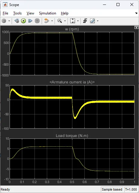
- There is a sudden spike in the armature current in 0 sec and 0.5 sec in both directions
- As the polarity changes the speed of the motor also changed
The following is the output obtained from the Current block, which contains the IGBT Current and the Diode current;
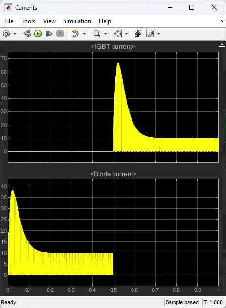
from the above graph, we can see that, for 0 to 0.5 sec, the current flows through diode D3 and from 0.5 sec to 1 sec, the current flows through Q3.
The motor starts in the positive direction with a duty cycle of 75% (mean DC voltage of 180V). At t= 0.5 sec., the armature voltage is suddenly reversed and the motor runs in the negative direction.
B. Comment on the armature current shoot-up from the scope results.
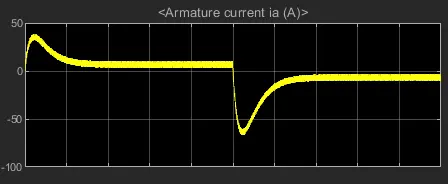
- At the start, there is a sudden spike in the armature current at 0 sec and 0.5 sec due to the transition from a positive to a negative direction of rotation
- This occurs due to the transient switching in the circuit
- It can be reduced by changing the duty cycle from 75% to 50 %
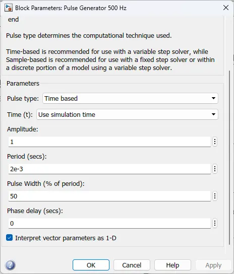
The varied results are shown below;
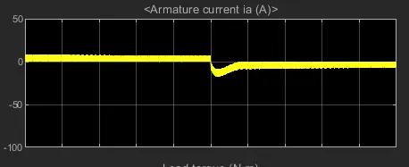
The armature current shoot-up reduces by 50% duty cycle
C. Refer to the help section of ‘The Four-Quadrant Chopper DC Drive (DC7) block’. Compare it with the H-bridge model.
- 'dc7_example' this command is used to load the model in the Simulink window
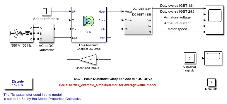
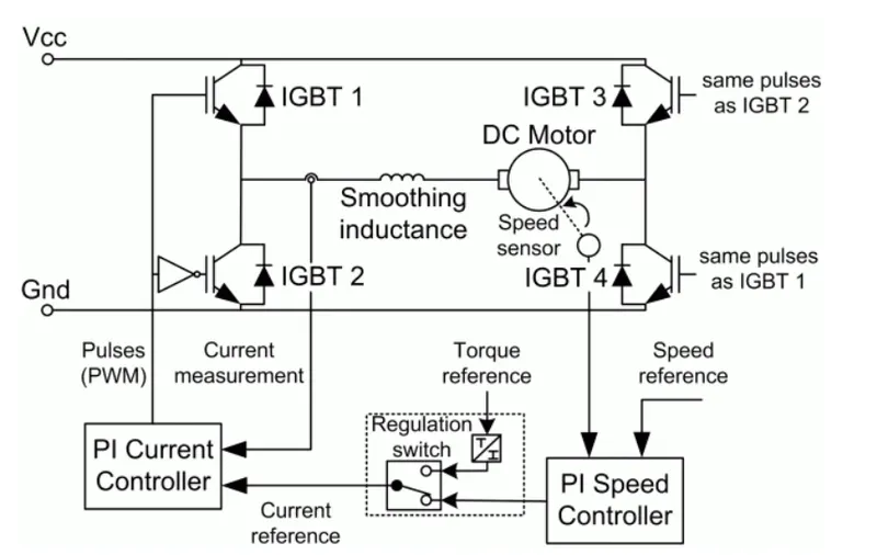
- The four-Quadrant chopper DC Drive (DC7) block represents a DC-DC PWM converter for DC motors
- Closed-loop speed control with the four-quadrant operation
- The speed control loop outputs the reference armature current of the machine
- The chopper duty cycle corresponding to the commanded armature current is derived using the PI controller
- The duty cycle is then compared with a sawtooth carrier signal to obtain the required PWM signals for the chopper
- It can operate in all four quadrants (forward motoring, reverse regeneration, reverse motoring, and forward regeneration)
- Due to the use of high switching frequency DC-DC converters, a lower armature current ripple is obtained
Comparison with the H-bridge model
| Aspect | H-Bridge | Four_quadranrt chopper |
| Modes |
|
|
| Control |
|
|
| Switching Frequency |
|
|
| Armature Current |
|
|
| Applications |
|
|
2. Develop a 2-quadrant chopper using Simulink & explain the working of the same with the relevant results. (Refer to the article - Multiquadrant operation of motor )
2-quadrant chopper
- The 2-quadrant chopper is also called a type c chopper ( type –A and type –B choppers in parallel)
- Always get a positive output voltage `V_0`
- When the diode starts conducting the `V_0`becomes `V_s`
- Operate as a type-A chopper in the first quadrant
- Operate as a type-B chopper in the second quadrant
- The average voltage will be always positive
- The average load current will be positive or negative
- There will be a short circuit if the two choppers are turned on together
- For regenerative braking and motoring these type of chopper configuration is used
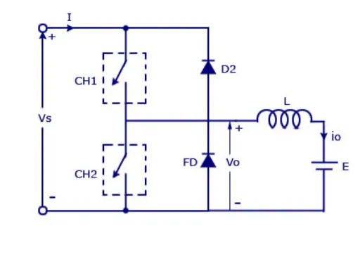
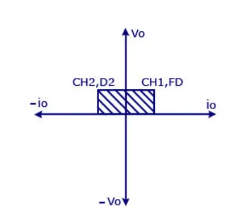
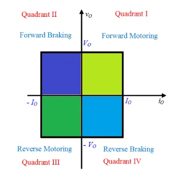
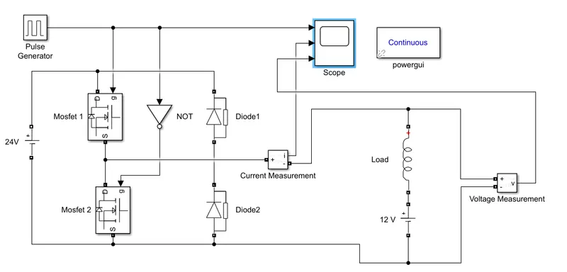
2-quadrant chopper using Simulink
Blocks used;
- Mosfet
- DC voltage source
- Diode
- Inductor
- Scope
- Voltage and current measurements
- Power GUI
Simulink Model
- DC voltage source be 24V
- Select Inductor(L) only option from the series RLC branch block
- Let the motor load be 12V in series with the Inductor
- A pulse generator is set up (with an amplitude of 10, a period of 0.02 seconds and a pulse width of 50%) as the gate pulse
Simulation Results
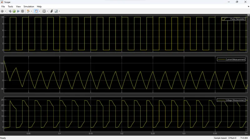
- The voltage is not going below zero
- Voltage is always positive
- The current varies from positive to negative
3. Explain in brief the operation of the BLDC motor.
BLDC Motor
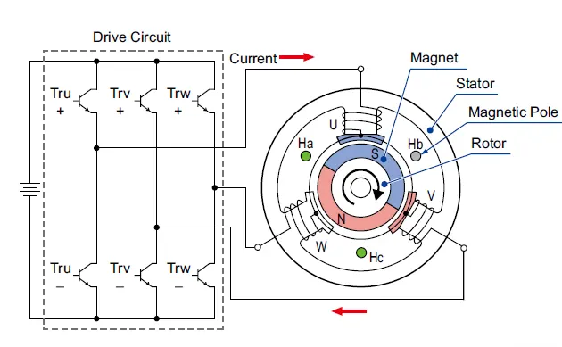
A Brushless DC (BLDC) motor is a type of electric motor that uses a permanent magnet rotor and electronically controlled commutation instead of brushes to control the direction and speed of the motor rotation.
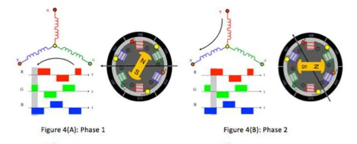
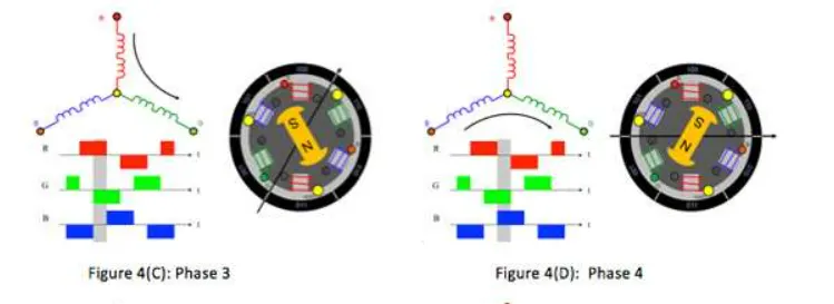
The operation of a BLDC motor involves the use of a controller that sends electronic signals to the motor's coil to energize them in a specific sequence. This sequence creates a rotating magnetic field that interacts with the permanent magnet rotor to produce torque and rotation.
The controller determines the motor's speed and direction of rotation by adjusting the timing and duration of the signal to the coils. The controller also regulates the current to the motor to prevent overheating and ensure efficient operation.
The simplified diagram of the BLDC motor is shown below;
Working of a BLDC Motor
-
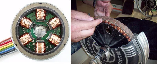
The BLDC motor has a stator with multiple coils arranged in a specific pattern, and a rotor with permanent magnets.
-
A controller sends electronic signals to the coils in the stator to energize them in a specific sequence, which creates a rotating magnetic field.
-
The rotating magnetic field interacts with the permanent magnets in the rotor, producing torque and rotation.
-
The controller regulates the current to the motor to ensure efficient operation and prevent overheating.
-
The controller adjusts the timing and duration of the signals to the coils to control the motor's speed and direction of rotation.
-
The controller may also include feedback mechanisms, such as sensors or encoders, to provide precise control of the motor's position and speed.
-
The BLDC motor can be used in a wide range of applications, including robotics, electric vehicles, and industrial machinery.
The advantages and Disadvantages of the BLDC motor are listed below;
| Advantages | Disadvantages |
|
|
Conclusions
1. A. Studied MATLAB demo model named ‘Speed control of a DC motor using BJT H-bridge’.
B. Studied the reason for the Armature current shoot-up from the scope results.
C. Studied ‘The Four-Quadrant Chopper DC Drive (DC7) block’.and compared it with the H-bridge model.
2. Developed a 2-quadrant chopper using Simulink & analysed results.
3. Studied the operation of the BLDC motor.
References
https://www.mathworks.com/help/sps/ug/speed-control-of-a-dc-motor-using-bjt-h-bridge.html
https://in.mathworks.com/help/sps/ug/dc7-four-quadrant-chopper-200-hp-dc-drive.html