Week-6 Challenge: EV Drivetrain
1. Which types of power converter circuits are employed in electric and hybrid electric vehicles?
In electric and hybrid electric vehicles, various types of power converters are used to control the flow of electrical energy between the battery pack and the electric motor, as well as between the grid and the vehicle battery pack. Some of the common types of power converter circuits used in EVs and HEVs are:
DC-DC Converter: A DC-DC converter is used to step down the high voltage from the battery pack to a lower voltage that can be used to power the vehicle's low-voltage electronics accessories.
The DC-DC Converter is classified into;
- Buck Converter: It is a step-down converter and produces a lower average output voltage than the dc input voltage.
- Boost Converter: In this, the output voltage is always greater than the input voltage.
- Buck-Boost converter: In a buck-boost converter, the output voltage can be either higher or lower than the input voltage.
- Cuk Converter: The output voltage can be either higher or lower than the input voltage providing some advantages over buck-boost (like a continuous current, less current ripple etc.)
- SEPIC converter: The output voltage can be either higher or lower than the input voltage (with no polarity reversal compared to Buck-boost or Cuk converter).
- AC-DC Converter(Charger): An AC-DC converter, also known as a charger, is used to convert the AC grid voltage to a DC voltage that can be used to charge the vehicle battery pack.
DC-AC Inverter: A DC-AC inverter is used to convert DC voltage from the battery pack to an AC voltage that can be used to power the motors in EVs and HEVs.
Bidirectional DC-DC Converter: A bidirectional DC-DC converter is used in HEVs to allow for energy transfer in both directions, from the battery pack to the electric motor and from the motor to the battery pack during regenerative braking.
Battery Management System(BMS): The BMS is a complex power converter circuit that manages the charging and discharging of the vehicle's battery pack. It monitors the battery voltage, temperature, and state of charge and provides feedback to the vehicle's control system to ensure that the battery is being used efficiently and safely.
2. An Electric Vehicle's powertrain with a 72V battery pack is shown in the diagram below. The duty ratio for the acceleration operation is 'd1' and for the braking operation the duty ratio is 'd2'.
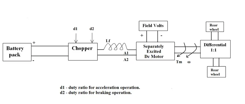
The other parameters of the electric vehicle are given below,
Motor and Controller Parameters:
Rated Armature voltage `V=72" votls"`
Rated armature current `I_a=400" A"`
Armature Resistance `R_a=0.5Omega`
Motor constant `K_phi=0.7" V/s"`
Chopper Switching frequency `f=400" Hz"`
The vehicle speed-torque characteristics are given by the below equation
`tau_v=24.7+(0.0051)omega^2`
What is EV steady state speed if the duty cycle is 70%?
as the duty cycle `d=70%`
The average voltage of the battery pack becomes `V_(avg)=Vxxd`
`V_(avg) =72xx70/100=50.4" V"`
The speed-torque characteristics of the motor is;
`tau_m=(V_(avg)*K_phi)/R_a-((K_phi)^2*omega)/R_a`
as,
`tau_v=tau_m`
we get,
`24.7+(0.0051)omega^2=(V_(avg)*K_phi)/R_a-((K_phi)^2*omega)/R_a`
`24.7+(0.0051)omega^2=(50.4xx0.7)/0.5-((0.7)^2*omega)/0.5`
`24.7+(0.0051)omega^2=70.56-0.98omega`
`0.0051omega^2+0.98omega-45.86=0`
this is the form of a quadratic equation
we found the roots using the Matlab command as shown below:
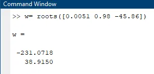
we get,
`omega_1=-231.07" rad/s"`
`omega_2=38.92" rad/s"`
we only consider the forward direction speed of the motor, so
`omega=38.92" rad/s"`
This can also be done with a Matlab code as given below;
%% Prompting the user to enter the Motor and Controller parametrs
fprintf("Enter Motor and Controller Parameters \n");
Va = input("Enter Armature Voltage(Volts)= ");
Ia = input("Enter Armature Current(Amperes)= ");
Ra = input("Enter Armature Resistance(ohms)= ");
K = input("Enter Motor Constant(V-s)= ");
d = input("Enter Duty cycle(Percentage)= ");

% Outpul Voltage calculations for the given duty cycle
d = d/100;
Vo = Va*d;

% The Vehicel torque Tv=24.7 + 0.0051*w^2
% The Motor torque Tm=((Va*k)/Ra) + ((k^2*w)/Ra)
% w is the angular speed in rad/s
%% Define the function to solve for w
fun = @(w) 24.7 + 0.0051*w^2 - ((Vo*K)/Ra) + ((K^2*w)/Ra); % at stead state condition Tm=Tv

% Use fsolve to find the root of the function
w_sol = fsolve(fun, 0);

%% Display the solution
disp('The angular speed in rad/s:');
disp(w_sol);
The Matlab code execution;
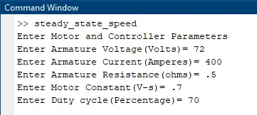
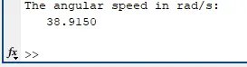
3. Develop a mathematical model of a DC Motor for the below equation using Simulink.
`omega= V/K_ϕ -R_a/K_ϕ^2 .T`
The Simulink model is shown below;
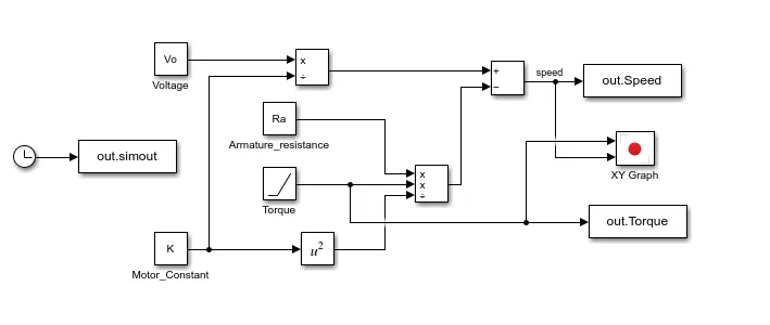
The Motor parameters are obtained from the above Matlab script.
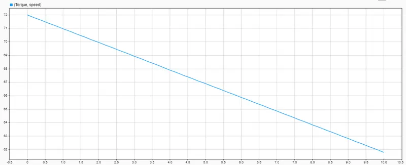
The Motor Speed-Torque Characteristics are shown below;
4. Refer to the blog on the below topic:
Induction Versus DC brushless motors by Wally Rippel, Tesla
Explain in brief the author’s perspective.
The article is a comparison between an Induction motor and DC brushless Motor done by Mr Wally Rippel, Principal Power Electronics Engineer on January 9th,2007.
This article is about the differences and similarities between a DC brushless Motor and Induction Motor. They are virtually identical, Both have three sets of “distributed windings” that are inserted within the stator core. The essential difference between the two machines is the rotor.
| Induction Motor | DC Brushless Motor |
|
|
peak point energy efficiency for a DC brushless drive will typically be a few percentage points higher than for an induction drive.
The author's conclusion is that DC brushless drives will likely continue to dominate in the hybrid and coming plug-in hybrid markets, and that induction drives will likely maintain dominance for the high-performance pure electrics, as the DC brushless drives had more advantages than the Induction Motor drives.
Conclusions
1. Studied the types of power converter circuits employed in electric and hybrid electric vehicles.
2. Founded the EV steady state speed when the duty cycle is 70% for given Motor and Controller parameters. (Mathematically and using Matlab Code )
3. Developed a mathematical model of a DC Motor for the given equation using Simulink. (Graphical Representation)
4. Referred to the given blog on the below topic and explained briefly the author’s perspective.