Week-7 Challenge: DC Motor Control
A. Explain a MATLAB demo model named ‘Speed control of a DC motor using BJT H-bridge’.
Solution:
At first, to run the speed control model of a DC motor using BJT H-bridge in matlab, the command - (power_Hbridge) is run in the command window of MATLAB.
We get a simulink window of the model as shown below
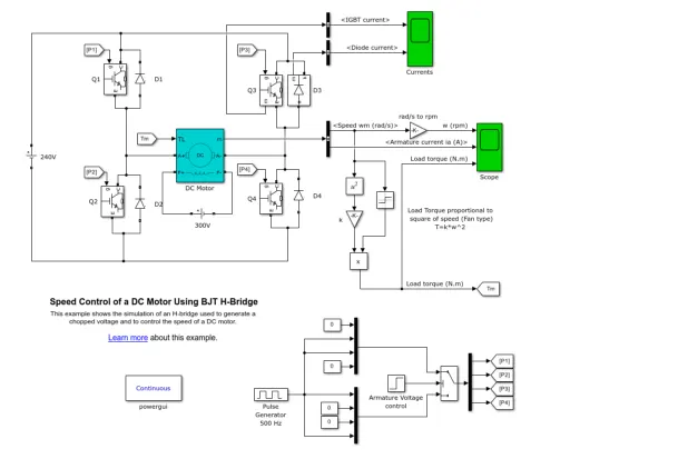
BJT H bridge construction and working:
BJT H bridge consists of 4 IGBT (Q1,Q2,Q3 and Q4) , 4 Diodes(D1,D2,D3&D4), PUlse generator which produces pulsated signals. These pulse signals are given as input to all the 4 Bjts. and we have DC motor connected in between Q1, Q2 and Q3 , Q4 as shown.
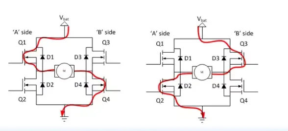
- The switch block is connected to pulse generator through armature voltage control block.
- The H-bridge consists of four BJT/Diode pairs (BJT simulated by IGBT models). Two transistors are switched simultaneously: Q1 and Q4 or Q2 and Q3. When Q1 and Q4 are fired, a positive voltage is applied to the motor and diodes D2-D3 operate as free-wheeling diodes when Q1 and Q4 are switched off. When Q2 and Q3 are fired, a negative voltage is applied to the motor and diodes D1-D4 operate as free-wheeling diodes when Q2 and Q3 are switched off.
The frequence of the switching is controled by the pulse generator block of the model. The pulse generator consists of inputs such as amplitude, period, pulse width (or) duty cycle and phase delay. The outputs of the pulse generator block are P1, P2, P3 and P4 which are connected to the BJT's. When the pulse width is changed, the results of the pulse generator changes which in turn control the output direction and speed of the motor.
- SWITCHES:
Q1 and Q4 - Forward motoring
Q2 and Q3 - reverse motoring
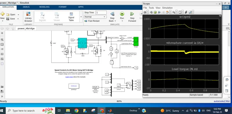
Scopes are attached accordingly to get the graphs of IGBT current, diode current, speed of the motor in (rpm), armature current in (A) and load torque in (N-m). The torque is calculated by using the relation between the torque and speed of a motor
There is default duty cycle of 75%, after running the model we will have graph of speed, armature current and torque. During the switching period at 0.5 sec from High to low we observe that there is spike or shoot up in the armature current. this is because of the transition of the signal from high to low.
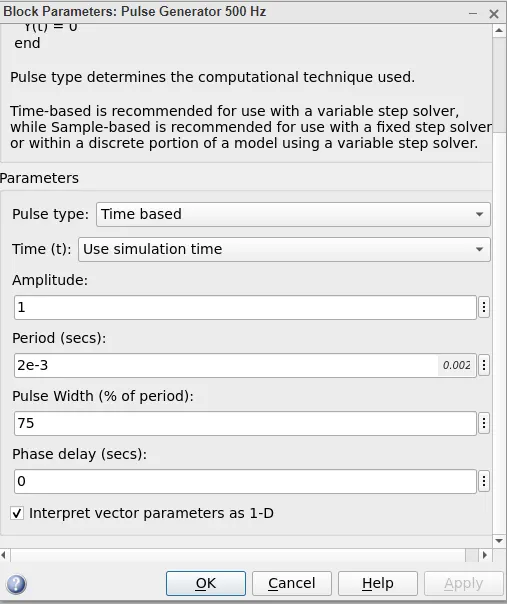
Save and run the model and click on the scope.
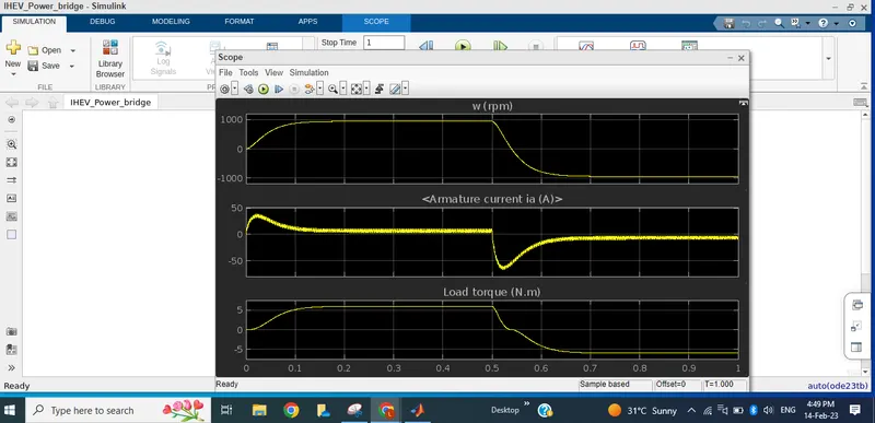
We can try to reduce the shoot up in aramture current by changing the pulse width to 50% from 75%, we can see there is reduction in the armature current shoot up to some extent.
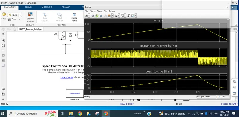
c) When pulse width changed to 25%, The graph has very neglizible overshoot, and the graph off all 3 factors are almost in straight line. The graph is shown below
B) Refer to the help section of ‘The Four-Quadrant Chopper DC Drive (DC7) block’. Compare it with the H-bridge model.
The Four-Quadrant Chopper DC Drive (DC7) block
The Dc7-four quadrent chopper 200 HP DC drive model is opened by running the command (dc7_example) using the command window of MATLAB.
The simulation window of the model is given below.
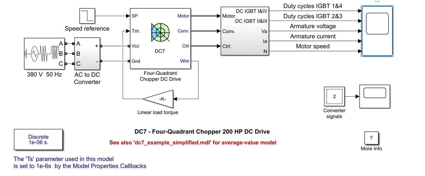
The 200 HP DC motor is separately excited with a constant 150 V DC field voltage source. The armature voltage is provided by an IGBT converter controlled by two PI regulators. The converter is fed by a 515 V DC bus obtained by rectification of a 380 V AC 50 Hz voltage source. In order to limit the DC bus voltage during dynamic braking mode, a braking chopper has been added between the diode rectifier and the DC7 block.
The first regulator is a speed regulator, followed by a current regulator. The speed regulator outputs the armature current reference (in p.u.) used by the current controller in order to obtain the electromagnetic torque needed to reach the desired speed.The speed reference change rate follows acceleration and deceleration ramps in order to avoid sudden reference changes that could cause armature over-current and destabilize the system.
The current regulator controls the armature current by computing the appropriate duty ratios of the 5 kHz pulses of the four IGBT devices (Pulse Width Modulation). For proper system behaviour, the instantaneous pulse values of IGBT devices 1 and 4 are opposite to those of IGBT devices 2 and 3. This generates the average armature voltage needed to obtain the desired armature current. In order to limit the amplitude of the current oscillations, a smoothing inductance is placed in series with the armature circuit.
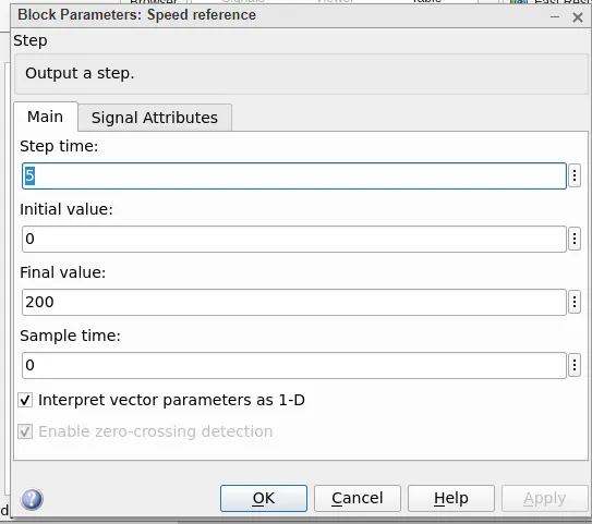
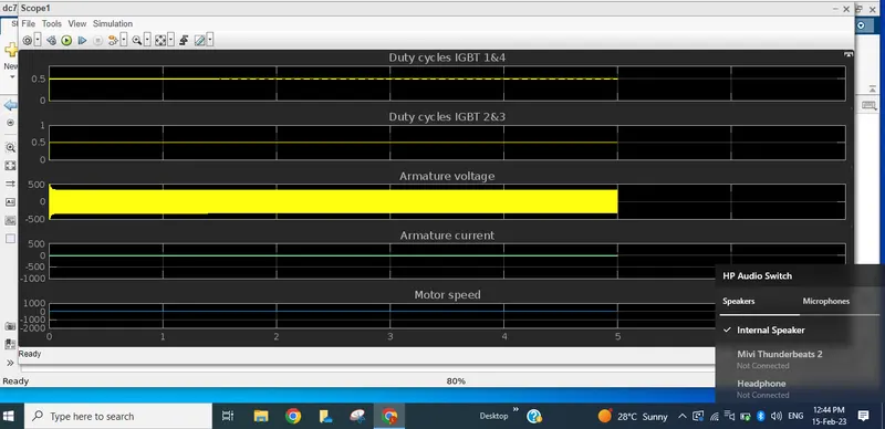
Here speed refernce parameter is changed as below
We can see below graph of armature current , armature voltage and speed. Armature current with no shoot up can be observed.
Difference between H bridge DC drive and 4 Quadrant DC7 drive
- Four-Quadrant Chopper can operates in all four modes (Forward Motoring,Forward Braking, Reverse Motoring and Reverse Braking), but H-bridge can operate only in two modes (Forward and Reverse).
- In Four-Quadrant Chopper Regenerative Braking is possible, but H-bridge Regenerative Braking is not possible
- In H bridge we observe over shoot in armature current at switching time.But not in 4 quadrant DC7 drive.
- In H bridge pulse generating input signals are directly applied on IGBT and diodes. But in DC7 drive we have controller with voltage regulator and current regulator.
2) Develop a 2-quadrant chopper using simulink & explain the working of the same with the relevant results. (Refer to article - Multiquadrant operation of motor )
Construction:
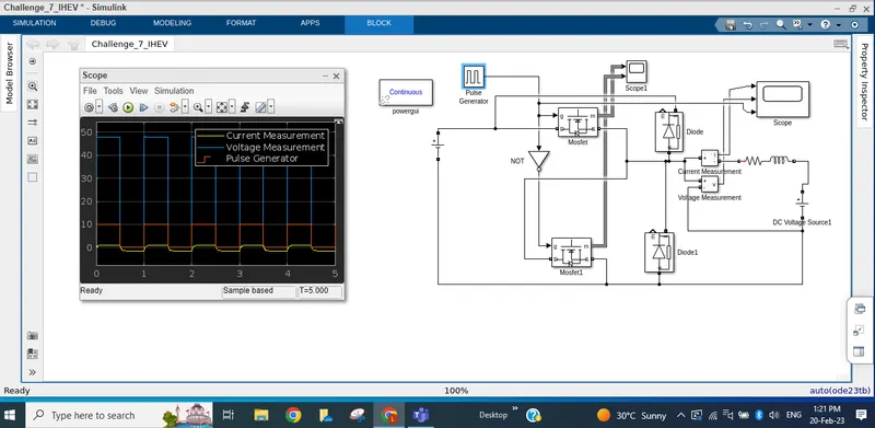
Power GUI, NOT Gate, 2 MOSFET, 2 Diodes, Voltage measurement , Ammeter measurement, DC input voltage, Pulse generator, RLC load branch , Back emf voltage.
DC input voltage:48V, Back emf voltage:30V , RLC load branch where R value is 20ohms and inductance value is 500mH.
A pulse generator is an input block provides Positive pulse input to MOSFET1 , use a NOT gate and reverse the signal (negative) and feed the input to MOSFET2, use diodes to pass the signals only in one direction. Then connect RLC load branch, connect a back emf to the load as shown below. Here capacitor value is kept to zero. R , L component value is configured. To measure the current and voltage output values connect ammeter in series and voltmeter in parallel with the load. Use Power GUI block if any simscape specialised component are used.
Two quadrant chopper is a converter , that works in 1st and 2nd quadrants only. In 1st quadrant Voltage and current are positive. In 2nd quadrant Voltage is positive and current is negative. From the graph we can observe Voltage is positive with amplitude. Current is both positive and negative.
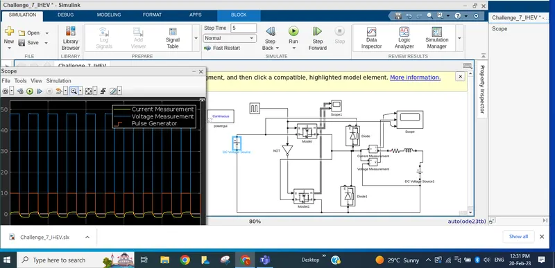
& Now pulse width is changed from 0.5 to 1.0 , output is as shown below.
3. Explain in a brief about operation of BLDC motor.
Soln: A brushless DC motor (also known as a BLDC motor or BL motor) is an electronically commuted DC motor which does not have brushes. The controller provides pulses of current to the motor windings which control the speed and torque of the synchronous motor.
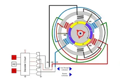
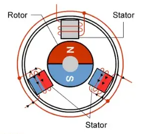
These types of motors are highly efficient in producing a large amount of torque over a vast speed range. In brushless motors, permanent magnets rotate around a fixed armature and overcome the problem of connecting current to the armature. Commutation with electronics has a large scope of capabilities and flexibility. They are known for smooth operation and holding torque when stationary.
Brushless DC motor has only two basic parts: rotor and the stator. The rotor is the rotating part and has rotor magnets whereas stator is the stationary part and contains stator windings. In BLDC permanent magnets are attached in the rotor and move the electromagnets to the stator. The high power transistors are used to activate electromagnets for the shaft turns. The controller performs power distribution by using a solid-state circuit.
The advantages of a BLDC motor are:
- Brushless motors are more efficient as its velocity is determined by the frequency at which current is supplied, not the voltage.
- As brushes are absent, the mechanical energy loss due to friction is less which enhanced efficiency.
- BLDC motor can operate at high-speed under any condition.
- There is no sparking and much less noise during operation.
- More electromagnets could be used on the stator for more precise control.
- BLDC motors accelerate and decelerate easily as they are having low rotor inertia.
- It is high performance motor that provides large torque per cubic inch over a vast sped rang.
- BLDC motors do not have brushes which make it more reliable, high life expectancies, and maintenance free operation.
- There is no ionizing sparks from the commutator, and electromagnetic interference is also get reduced.
- Such motors cooled by conduction and no air flow are required for inside cooling.
The disadvantages of a BLDC motor are:
- BLDC motor cost more than a brushed DC motor.
- The limited high power could be supplied to BLDC motor, otherwise, too much heat weakens the magnets and the insulation of winding may get damaged.