Week-7 Challenge: DC Motor Control
Question 1:
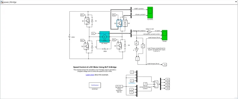
A. Explain a MATLAB demo model named ‘Speed control of a DC motor using BJT H-bridge’.
Answer:
A DC motor can be controlled by various power controller in that the BJT H-Bridge is one of power controller for DC Motor.
A H-Bridge is constructed in the shape of 'H' where the motor is place in the center of two vertical line. These two vertical line are constructed by the uses of power electronics like BJT, MOSFET and IGBT but in these circuit they user BJT power electronics. And these H-Bridge is connected to the DC Voltage.The Circuit given below.
H-Bridge is made for rotate the motor in two direction one is clockwise direction another is anti-clockwise direction. These can be achieved by the controlling of base(B) signal in BJT(Bipolar Junction Transistor).For an motor rotate in an clockwise direction or forward the Q1 and Q4 must be ON and Q2 and Q3 must be OFF.
For an motor rotate in an anti-clockwise direction or backward the Q2 and Q3 must be ON and Q1 and Q4 must be OFF.
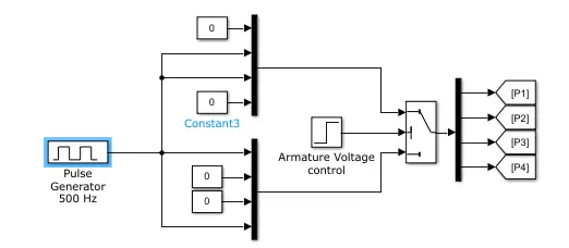
Where P1,P2,P3 and P4 are base that control the BJT, That controlled block diagram shows that if the armature voltage condition is TRUE then the P1 and P4 get the pulse generator input else the system take the no input is mention as '0'.
| Q1 | Q2 | Q3 | Q4 | Action |
| ON | OFF | OFF | ON | Forward |
| OFF | ON | ON | OFF | Backward |
| ON | OFF | ON | OFF | Short Circuit |
| OFF | ON | OFF | ON | Short Circuit |
***************************************************
B. Comment on the armature current shoot-up from the scope results.
Answer:
BJT is current controller device where an BJT is conected with diode in parllel connection and an pulse generator is an input for the system, Where BJT and diode convert an pulse input to an pure DC output but the DC motor controller change the voltage source for every 0.5 sec so the current flow direction also change for every 0.5 sec, The slope in the armature current graph shows that the pulse input increases and BJT try to achive an pure DC after some fraction of time clearly shown in a graph given below,
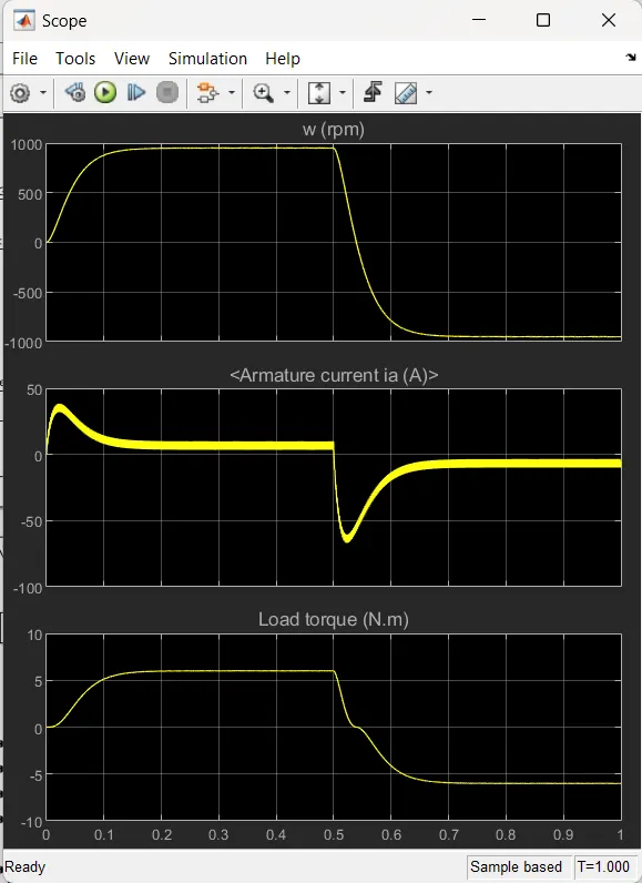
The Shoot-up value can be reduce by change the input pulse generator pulse width %.Where an pulse width percentage decreases the armature current shootup value can be gradually decreases.
***********************************************************
C. Refer to the help section of ‘The Four-Quadrant Chopper DC Drive (DC7) block’. Compare it with the H-bridge model.
Four-Quadrant Chopper DC Drive.
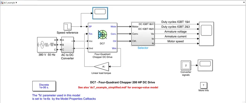
These is one of the DC motor controller. In these Four-Quadrant Chopper DC Drive it should take the reference speed and torque and control the DC motor. To control the speed of the DC motor the controller take the output speed and convert it into torque and feedback to the reference torque to maintain the required torque and speed.
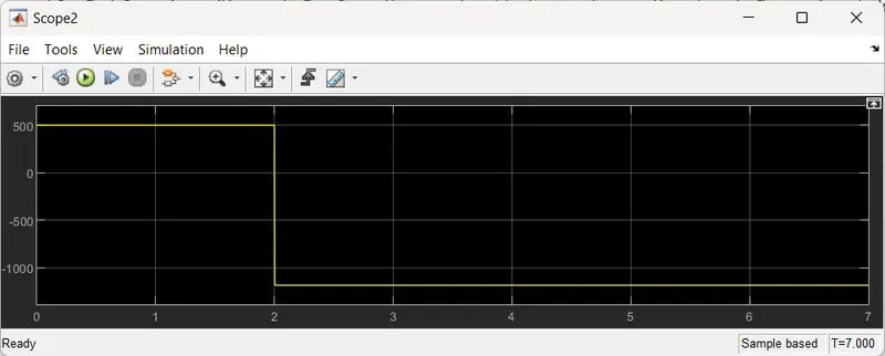
The reference speed for first 2 sec is positive and after 2 sec the speed suddenly goes to negative show in figure given below.
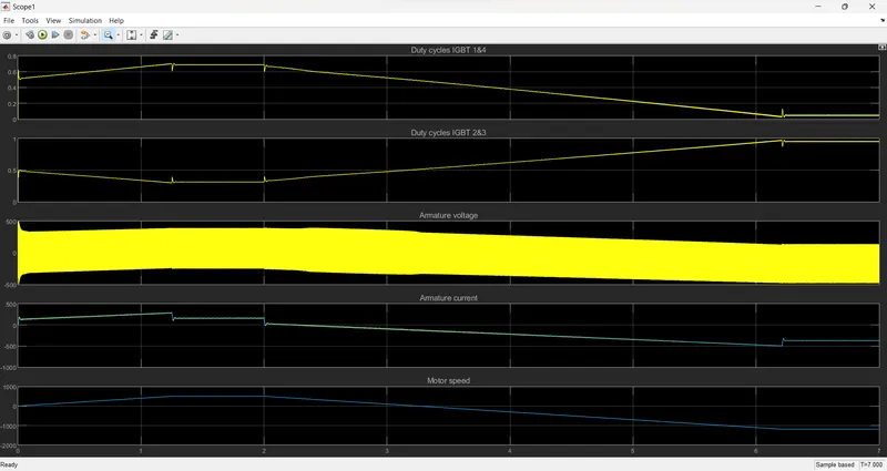
In the below graph, it shoes that the armature current is moving in positve direction for first 2 sec and after 2 sec it try to move to negative side so gradually the armature current shift towards the negative and reach the stability after 6.2 sec. These can be achieved by the reference speed input and it an also be absored in output speed graph.
Compare of H-Bridge with Four-Quadrant Chopper DC Drive
- An H-bridge need an separate gate controller design where an Four-Quadrant Chopper DC Drive required an speed reference.
- The Simulation time of H-bride is faster when compare to Four-Quadrant Chopper DC Drive because it has an complex circuit.
- The shifting time is also faster for H-Bridge when compare to Four-Quadrant Chopper DC Drive.
******************************************************************************************
Question 2:
Develop a 2-quadrant chopper using simulink & explain the working of the same with the relevant results. (Refer to article - Multiquadrant operation of motor )
Answer:
In this 2-quadrant chopper model, Here the IGBT is used as an Power controller device with an diode in parllel connection.
In an 2-quadrant chopper the flow of current is designed bu the pulse generator with an switch current is higlighted in purple box.
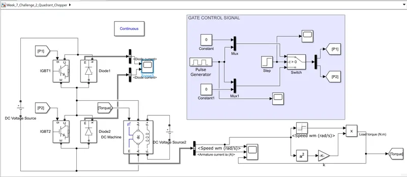
In 2 quardrant model,
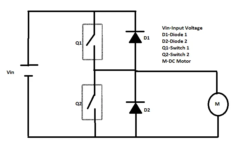
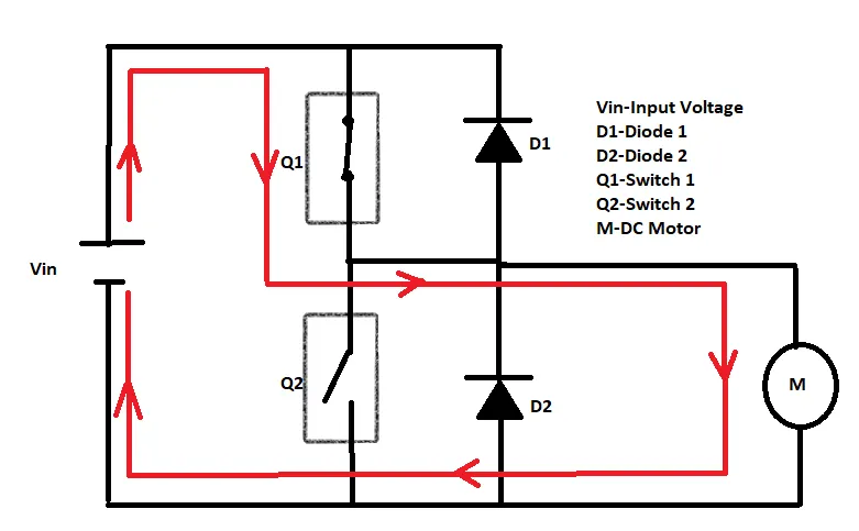
First quadrant is active when an Q1 signal is ON and Q2 signal is OFF, The flow of power is first reached the IGBT1 and flow throught the Diode 2 and reach the motor, So it rotate in clockwise direction.
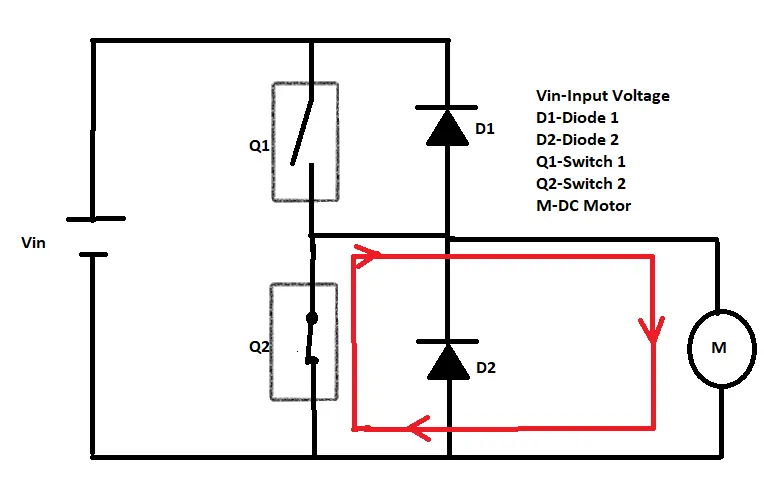
Second quadrant is active when an Q1 signal is OFF and Q2 signal is ON,The flow of power is first reached the Diode 1 and flow throught the IGBT2 and reach the motor, so it rotate in anticlockwise direction.
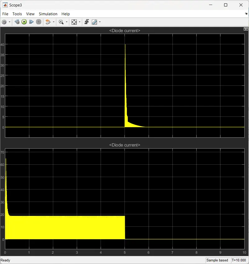
Current Flow in diode1 and diode2 is given below.
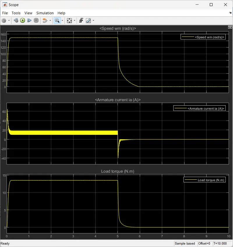
Output Graph:
******************************************************************************************
Question 3:
Explain in a brief about operation of BLDC motor.
Answer:
Construction:
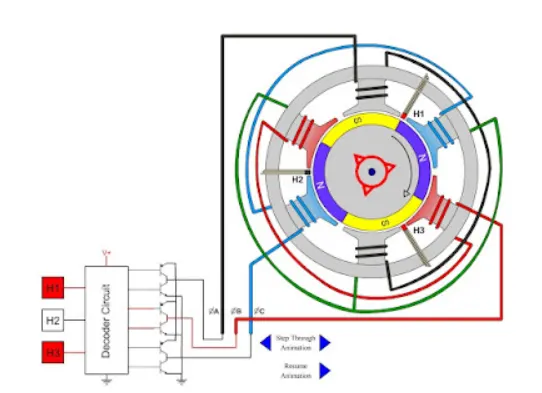
BLDC motor is contain stator and rotor,where rotor contains permanent magnet and stator contains copper winding and the Hall effect sensor are placed in between two stator to sense the magnetic effect , And winding is connected to an power controller to control the magnetic field of the stator coil with the flow of current direction, The special function of the motor shows there is no brushes are buit inside the motor so there is no spark loss.
Working:
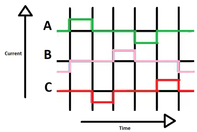
Where all the coils are not energiezed at same time, there are 3 coils are energized in controlled manner,In these model 2 coils are energized at same time with an opposite polarity so only the permanent magnet try to caught the opposite field and the field transfer from one coil to another.
The input to the coils can be controlled by implement the switch and Turn ON and OFF the switch at particular time interval to produce an magnetic field in the coil to control the speed of motor.
When the stator coils are electrically switched by a supply source, it becomes electromagnet and starts producing the uniform field in the air gap. Though the source of supply is DC, switching makes to generate an AC voltage waveform with trapezoidal shape. Due to the force of interaction between electromagnet stator and permanent magnet rotor, the rotor continues to rotate.
******************************************************************************************