DC Motor Control
Q1: Run MATLAB demo ‘Speed control of a DC motor using BJT H-bridge’. Modify the model such that armature current doesn’t shoot up when motor changes direction from forward to reverse.
Q2: Refer to help section of ‘The Four-Quadrant Chopper DC Drive (DC7) block’. Compare it with H-bridge model.
Q3: Make a suitable EV model using DC7 block and make result report.
A:
Aim: To run MATLAB od different power electronics and DC motor models. Comparing model each other results and concluding a result of motors in EV.
A1:
Theory:
Power Electronics: It is the application of solid state to the control and conversion of electric power. The first high power electronic devices were mercury arc valves. In modern systems, the conversion is performed with semiconductor switching devices such as diodes, thyristors, and power transistors such as the power MOSFET and IGBT. In contrast to electronic systems concerned with transmission and processing of signals and data, in power electronics substantial amounts of electrical energy are processed.
The power conversion systems can be classified according to the type of the input and output power:
- AC to DC
- AC to AC
- DC to AC
- DC to DC
Applications: Batteries, adapters, audio amplifiers, ballasts etc.
Duty cycle: A duty cycle or power cycle is the fraction of one period in which a signal or system is active. Duty cycle is commonly expressed as a percentage or a ratio. A period is the time it takes for a signal to complete an on-and-off cycle.
d = ON/total
Since, total = ON + OFF
Transistors: These are devices that have controlled turn-on and turn-off characteristics. These devices are used a switching devices and are operated in the saturation region resulting in low on-state voltage drop. They are turned on when a current signal is given to base or control terminal.
Bipolar Junction Transistor(BJT):
A BJT is a bipolar junction transistor, which is capable of handling two polarities (holes and electrons), it can be used as a switch or as an amplifier and also known as a current control device. The following are the characteristics of a power BJT, they are
- It has a larger size, so that maximum current can flow through it
- The breakdown voltage is high
- It has higher current carrying and high-power handling capability
- It has a higher on-state voltage drop
- High power application.
IGBT: As the name suggests an IGBT is a combination of FET and BJT transistor whose function is based on its gate, where the transistor can be turned on or off depending on the gate. They are commonly applied in power electronics devices like inverters, converters, and power supply. The following are the characteristics of Insulated-gate Bipolar transistor (IGBTs).
- At the input of the circuit, the losses are less
- higher power gain.
MOSFET: MOSFET has a thin layer of silicon dioxide, which acts as the plate of a capacitor. The isolation of the controlling gate raises the resistance of the MOSFET to extremely high levels almost infinite.
The gate terminal is barred from the primary current pathway; thus, no current leaks into the gate.
MOSFETs exist in two main forms:
-
Depletion state: This requires the gate-source voltage (VGB) to switch the component OFF. When the gate is at zero (VGB) the device is usually ON, therefore, it functions as a load resistor for given logic circuits. For loading devices with N-type depletion, 3V is the threshold voltage where the device is switched OFF by switching the gate at negative 3V.
-
Enhancement state: The gate-source voltage (VGB) is required in this state to switch the component ON. When the gate is at zero (VGB) the device is usually OFF and can be switched ON by ensuring the gate voltage is higher than the source voltage.
Model:
- Open 'Speed control of a DC motor using BJT H-bridge' model and run it for 1 second simulation time.
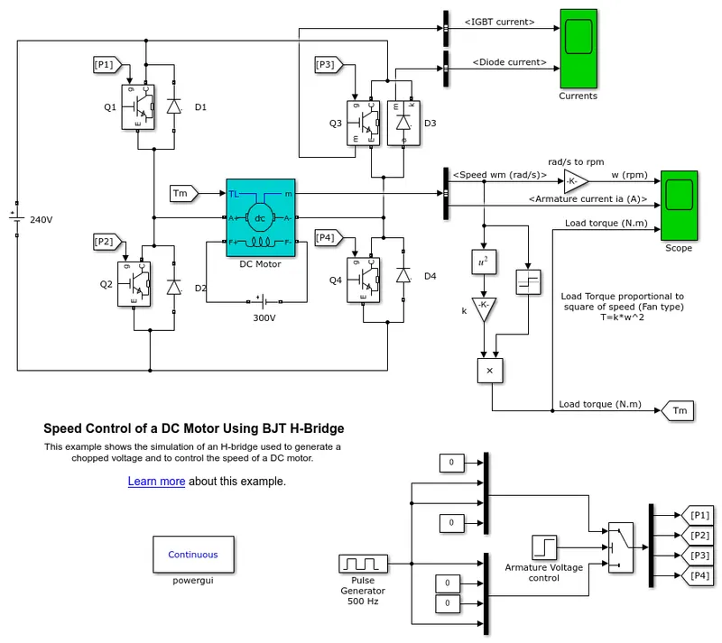
This model shows the simulation of an H-bridge used to generate a chopped voltage and to control the speed of a DC motor.
The Bipolar Junction Transistor (BJT) when used for power switching applications, operates as an IGBT. When it is conducting (BJT operating in the saturated region), a forward voltage Vf is developed between collector and emitter (in the range of 1 V). Therefore, the IGBT block can be used to model the BJT device.
The IGBT block does not simulate the gate current controlling the BJT or IGBT. The switch is controlled by a Simulink® signal (1/0). The DC motor uses the preset model (5 HP 24V 1750 rpm). It simulates a fan type load (where Load torque is proportional to square of speed). The armature mean voltage can be varied from 0 to 240 V when the duty cycle (specified in the Pulse Generator block) is varied from 0 to 100%.
The H-bridge consists of four BJT/Diode pairs (BJT simulated by IGBT models). Two transistors are switched simultaneously: Q1 and Q4 or Q2 and Q3. When Q1 and Q4 are fired, a positive voltage is applied to the motor and diodes D2-D3 operate as free-wheeling diodes when Q1 and Q4 are switched off. When Q2 and Q3 are fired, a negative voltage is applied to the motor and diodes D1-D4 operate as free-wheeling diodes when Q2 and Q3 are switched off.
The motor starts in the positive direction with a duty cycle of 75% (mean DC voltage of 180V). At t= 0.5 sec., the armature voltage is suddenly reversed and the motor runs in the negative direction.
Model results:
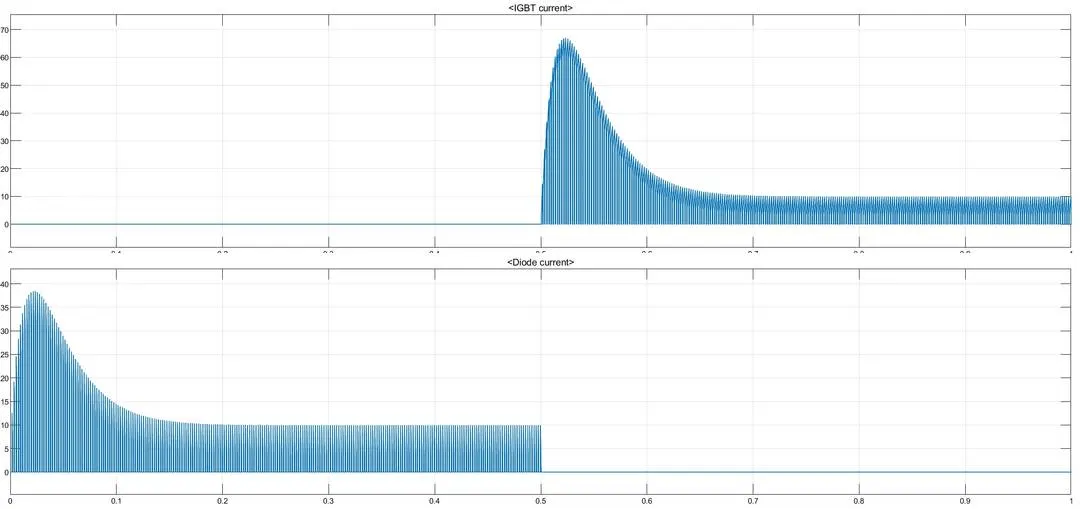
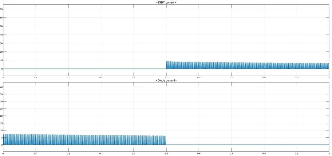
- In the results scope, we can observe that after 0.5 seconds the IGBT current starts flowing.
- The current starts flowing in diode initially upto 0.5 seconds.
- There is no passage of diode current which indicates that current may passing in reverse direction.
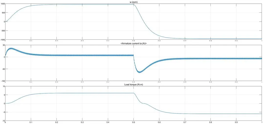
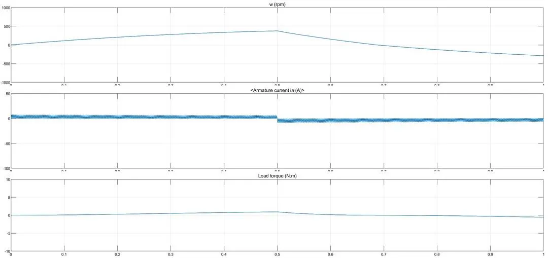
- We can observe initially the speed is increased to top and maintains upto 0.5 seconds. After that it is reduced and goes to negative.
- After 0.5 seconds we can observe armature current shoots up.
- The load also decreases after 0.5 seconds.
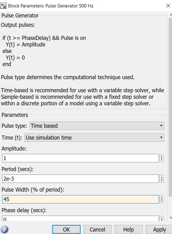
Change the duty cycle, So that the the motor changes its direction from forward to reverse and armature current doesn't shoot up. Change pulse width from 75% to 45%.
Results for second condition:
- We can observe switching for 45% pulse width.
- We can observe that armature current doesn't shoot up.
- Instead of sudden decrease, there is a slow decrease in speed and load torque after 0.5 seconds.
- The variations are less when compared with high duty cycle.
A2:
Comparing model DC7 chooper to H-bridge:
DC 4 quadrant chopper:
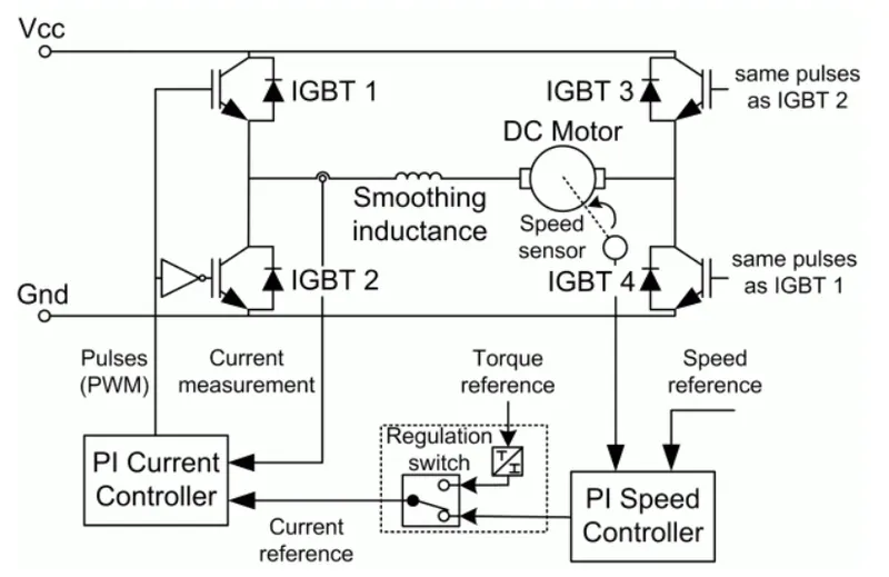
- The armature voltage is provided by IGBT controllers is controlled by two PI regulators.
- A braking chopper has been added between the diode and motor.
- This model contains speed and current regulators.
- The speed regulator represents ramature current used by the current controller in order to obtain the electromagnetic torque needed to reach the desired speed.
- The chopper converts the fixed DC voltage to variable DC voltage.
- It requires current for each sector and consists of four quadrant motoring, forward motoring, forward regenrative braking , reverse motoring, and regenrative reverse braking.
- Current signal is interrupted with one other to chnage the dorection of the motor.
- The change in direction in BJT is done by changing the polarity.
- PID controller is used in DC7 model.
H-bridge model:
- It consists of two operations forward motoring and reverse motoring.
- It is used in robotics technology.
- PID controllers are not used in this model.
- It operates in 2 quadrants.
- In this model the current chnages as there is a change in the polarity in switches.
- This model is discrete.
- Speed controller and current controller sampling times are present.
- The current shoot up and disturbances are high in this due to switching.
The Four-Quadrant Chopper DC Drive block uses these blocks from the Electric Drives/Fundamental Drive Blocks library:
-
Speed Controller (DC)
-
Regulation Switch
-
Current Controller (DC)
-
Chopper
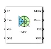
Block of for quadrant chopper DC drive:
A3: Building an EV model using DC7 motor:
- To build an EV model we use DC7 four quadrant motor.
- Open DC7 four qudrant motor 200 HP model.
- Remove blocks of sources and torque input.
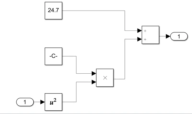
- Create a subsystems for defined equation i.e., T = 24.7 + 0.0051ω^2.
- Create blocks for this relation and join with DC motor.
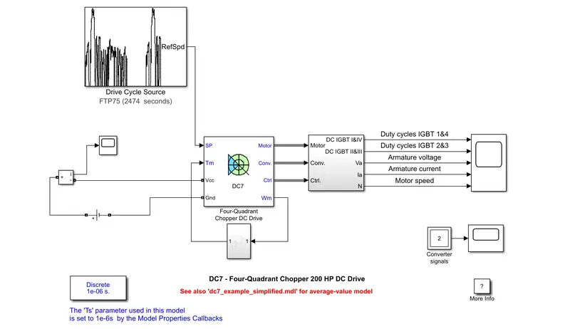
- We need a new drive cycle instead of using step generator.
- Use default drive cycle (FTP75) and give as input.
- The sources are given by voltage sources and for current measurement, we use current measurement block.
- Join all connections as shown below model adn run for simulation of 1 sec.
Various connections made to build an EV model.
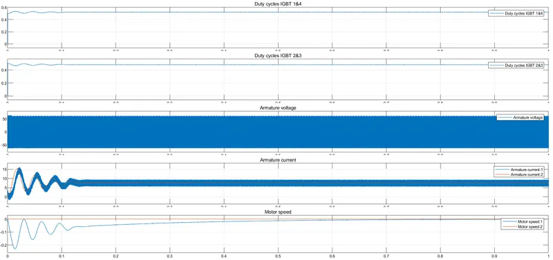
Results:
- We can observe the results obtained for model simulation .
- Duty cycle for four IGBTs are shown.
- The armature current and motor speed are varied initially and voltage is maintaned same.
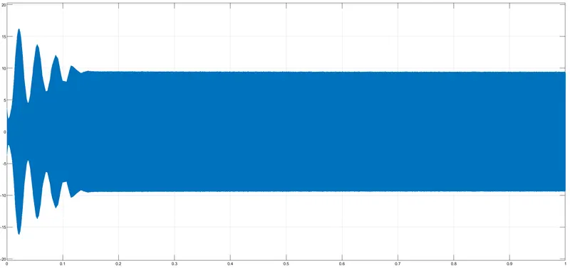
Input voltage supply scope:
Conclusion:
- Running Speed control of a DC motor using BJT H-bridge model and making chnages in duty cycles to stop armature current shooting up.
- Studying on The Four-Quadrant Chopper DC Drive (DC7) block and comparing it with H-bridge.
- Building an EV model using DC7 block and simulating the model.
References:
https://en.wikipedia.org/wiki/Power_electronics
https://skill-lync.com/knowledgebase/how-to-model-dc7-four-quadrant-chopper-200-hp-dc-drive