Week-7 Challenge: DC Motor Control
Q: Explain a MATLAB demo model named ‘Speed control of a DC motor using BJT H-bridge’. Comment on the armature current shoot-up from the scope results. Refer to the help section of ‘The Four-Quadrant Chopper DC Drive (DC7) block’. Compare it with the H-bridge model.
BJT or bipolar juntion transistor is solid state device in which current flows between two terminals the collector and emitter and is controlled by the amount of current through the base which is the third terminal.
H-bridge is an electronic circuit that switches the polarity of the voltage applied to load. It is often used in robotics and in DC motor to run forward or backwards.
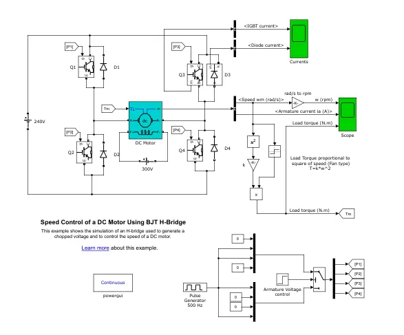
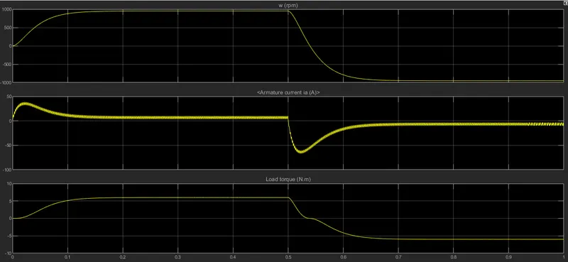
This example shows the simulation of an H-bridge used to generate a chopped voltage and to control the speed of a DC motor. The motor starts in positive direction with duty cycle of 75%, at t=0.5s the armature voltage is suddenly reversed and motor runs at negative direction.
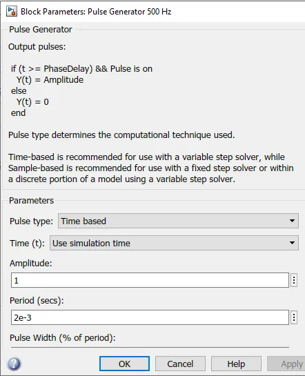
The pulse generator block gives 75% duty cycle as shown
Graph of duty cycle at 75%
Graph of duty cycle at 50%
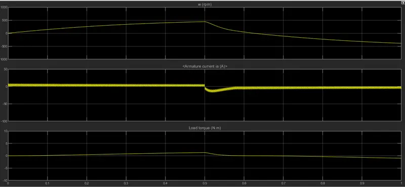
Graph of duty cycle at 40%
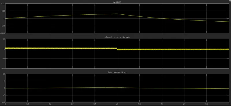
Conclusion: lowering the duty cycle the current shooting is reduced. For lowering the current shooting we have to increase the resistance of the diode. To get steady and smooth current flow we need to decrease and control duty cycle.
Refer to the help section of ‘The Four-Quadrant Chopper DC Drive (DC7) block’. Compare it with the H-bridge model.
The four quadrant chopper operates in four quadrants. They are forward braking, forward motoring, reverse braking and reverse motoring.
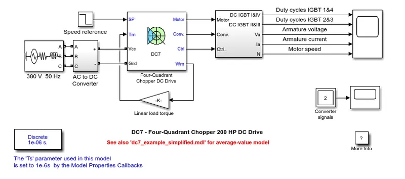
Comparison of four quadrant chopper and H-bridge
- The four quadrant chopper is used to change the motor direction hence the polairty is changed, whereas H-bridge to change the motor direction the current signal has to be interrupted.
- Four quadrant chopper has broader torque and power output ranges. In H-bridge it uses single pulse generator which gives narrow torque and power output range.
- Four quadrant chopper uses upto 400v wheras H-bridge uses 350v
- In four quadrant chopper regenerative braking is possible, wheras in H-bridge it is not possible.
Q: Develop a 2-quadrant chopper using simulink & explain the working of the same with the relevant results.
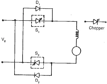
Two quadrant chopper simulink block: blocks used are power gui, pulse generator, not gate, 2 mosfet, 2 diode, 2 dc voltage source, current measurement, inductor load, voltage measurement and scope.
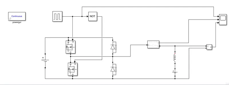
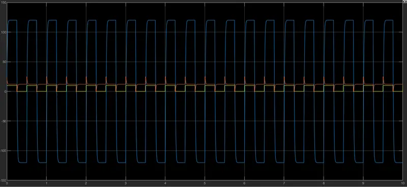
Operation of a 2-quadrant chopper: Sometimes a chopper may be required to provide a two quadrant operation by retaining the current direction in both motoring and braking modes. The chopper permits a change in the polarity of terminal voltage keeping the direction of current constant. In Fig. 3.86 S1 and S2 are the choppers working as electronic switches and D1 and D2 are the feedback diodes. Assuming continuous conduction, both S1 and S2 operate simultaneously.
When they are ON, the load current Id increases, with the rate of rise depending upon the back emf and torque of the machine. When they are OFF, the load current is fed to the supply through the diodes D1 and D2. The current decreases in this stage. From below image, it is clear that the load voltage is effectively negative when the diodes conduct. The average value of the output voltage of the chopper
Q: Explain in a brief about operation of BLDC motor.
Brushless DC motors are common in industrial applications across the world. At the most basic level, there are brushed and brushless motors and there are DC and AC motors. Brushless DC motors, as you may imagine, do not contain brushes and use a DC current.
It often helps to explain how a brushed DC motor works first, as they were used for some time before brushless DC motors were available. A brushed DC motor has permanent magnets on the outside of its structure, with a spinning armature on the inside. The permanent magnets, which are stationary on the outside, are called the stator. The armature, which rotates and contains an electromagnet, is called the rotor.
In a brushed DC motor, the rotor spins 180-degrees when an electric current is run to the armature. To go any further, the poles of the electromagnet must flip. The brushes, as the rotor spins, make contact with the stator, flipping the magnetic field and allowing the rotor to spin a full 360-degrees.
A brushless DC motor is essentially flipped inside out, eliminating the need for brushes to flip the electromagnetic field. In brushless DC motors, the permanent magnets are on the rotor, and the electromagnets are on the stator. A computer then charges the electromagnets in the stator to rotate the rotor a full 360-degrees.
Construction of Brushless DC motor
In this motor, the permanent magnets attach to the rotor. The current-carrying conductors or armature windings are located on the stator. They use electrical commutation to convert electrical energy into mechanical energy.
The main design difference between a brushed and brushless motors is the replacement of mechanical commutator with an electric switch circuit. A BLDC Motor is a type of synchronous motor in the sense that the magnetic field generated by the stator and the rotor revolve at the same frequency.
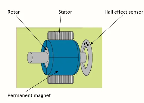
Brushless motor does not have any current carrying commutators. The field inside a brushless motor is switched through an amplifier which is triggered by the commutating device like an optical encoder.
The layout of a DC brushless motor can vary depending on whether it is in “Out runner” style or “Inrunner” style.
-
Outrunner – The field magnet is a drum rotor which rotates around the stator. This style is preferred for applications that require high torque and where high rpm isn’t a requirement.
-
In runner – The stator is a fixed drum in which the field magnet rotates. This motor is known for producing less torque than the out runner style, but is capable of spinning at very high rpm.
Working principle
BLDC motor works on the principle similar to that of a brushed DC motor. The Lorentz force law which states that whenever a current carrying conductor placed in a magnetic field it experiences a force. As a consequence of reaction force, the magnet will experience an equal and opposite force. In the BLDC motor, the current carrying conductor is stationary and the permanent magnet is moving.
When the stator coils get a supply from source, it becomes electromagnet and starts producing the uniform field in the air gap. Though the source of supply is DC, switching makes to generate an AC voltage waveform with trapezoidal shape. Due to the force of interaction between electromagnet stator and permanent magnet rotor, the rotor continues to rotate.
With the switching of windings as High and Low signals, corresponding winding energized as North and South poles. The permanent magnet rotor with North and South poles align with stator poles which causes the motor to rotate.