Week -2
Q: Make a Simulink model of Doorbell using solenoid block with the following details: In the above arrangement, when the switch is closed the electromagnet receives electrical power from the battery and pulls the metal arm to hit the bell producing sound. Create a situation where the switch is closed for 2 seconds and then released. Observe the physical movement of the plunger. Assume remaining parameters.
Block diagram of doorbell using solenoid block
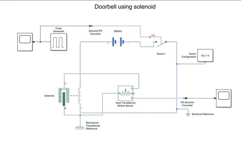
- The blocks used in model are scope, pulse generator, battery, switch, solenoid, ideal translational motion sensor and solver configuration.
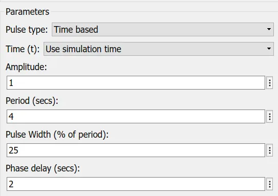
- We are using a pulse generator in order to close the switch for 2s with a pulse width of 25.
- A switch is connected to the negative terminal of the battery and a solenoid to positive terminal. Pulse generator signal is converted using simulink-PS converter which is given to input to the switch.
- The solenoid is measured using an ideal translational motion sensor.
- The output from the ideal translational motion sensor is converted using PS-simulink converter.
Input
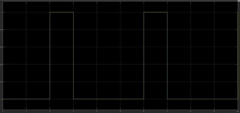
Output obtained based on the above parameters
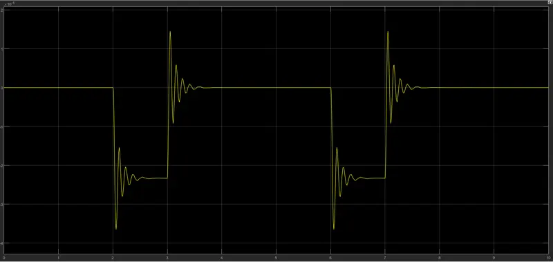
Conclusion: A simulink model of doorbell using solenoid block is created and the output is generated using motion sensor.
Q: Use a thermistor to sense the temperature of a heater & turn on or turn off the fan as per the below conditions:
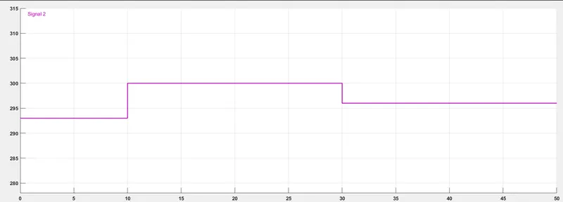
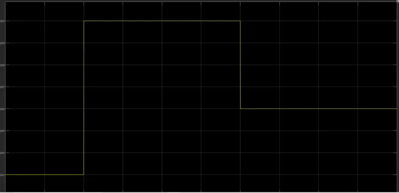
Temperature source: 20 °C from 0 to 10 seconds, 27 °C from 10 to 30 seconds, 23 °C from 30 to 50 seconds
Fan conditions: ON if the temperature above 25 °C, OFF otherwise.
Simulink block
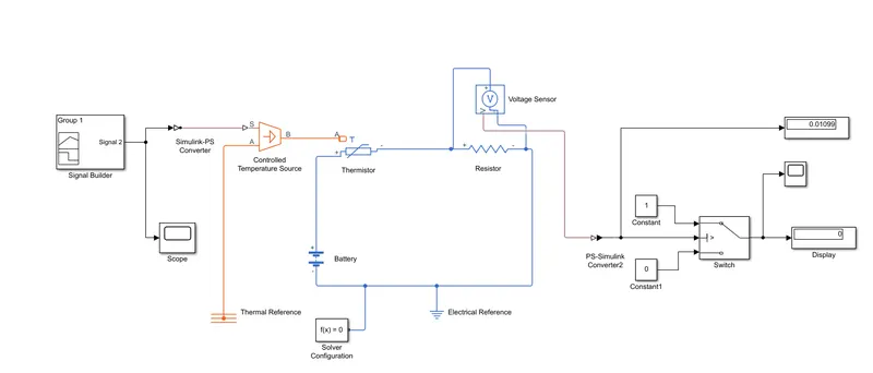
- The input values is given by signal builder as per the above requirements
- The input signal is fed to Controlled Temperature Source through a simulink-PS converter. Scope block is connected to check the input signal.
- The signal is fed into port-A of the thermistor. The positive terminal of thermistor is connected to the positive terminal of battery and negative terminal of thermistor is connected to the resistor and voltage sensor.
- The negative terminal of the battery and voltage sensor is connected electrical reference and its grounded.
- The voltage sensor is connected to scope and switch through a PS-simulink converter.
- To turn ON the fan if the temperature is above 25 degree celsius we have used a switch with threshold value of 0.01189.
Output
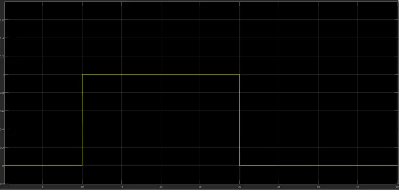
From the above result it is obtained that if the temperature is greater than 298 K the fan is On otherwise it is turned off.