Week - 4
Q: To implement control logic of a “washing machine” using Stateflow as per given sequence:
- If the power supply is available, the system gets activated
- If the Water supply is not available, stop the process & indicate through LED
- Soaking time should be 200s followed by Washing time of 100s.
- Then rinsing happens for next 20s & dryer runs for 50s
Principle of washing machine: The main principles behind the working of a washing machine are the centrifugal and centripetal forces, Where centrifugation helps quicken the process of sedimentation of different density particles to clean the laundry in the washing machine. The washing machine operates in two primary cycles. These are the wash cycle and the rinse cycle.
- The wash cycle involves the principle of centrifugal force. This force’s direction is from inside to outside, which makes sure that every part of the cloth is rinsed adequately in the soap water mixed in the machine.
- The rinse cycle involves the principle of centripetal force. This force acts from outside to inside and creates a vacuum-like space in the middle of the washing machine.
These two cycles work one after another several time, and as a result, the entire cleaning process occurs.
Step by step mechanism of the working of washing machine
Firstly before the washing machine starts to operate, you need to get it ready for the washing. Getting the machine ready includes filling the washing machine with water held in the outer drum and stopping the water from leaking while operating. Then you put the clothes inside the inner drum.
- The inner drum is the drum on which the different forces will give you a cleaner version of your clothes. Then you put the detergent into the machine, and after plugging in the device, we are ready to go.
- There is a thermostat present inside the washing machine. After you turn on the device, the thermostat measures the temperature and increases the heat according to its need. When the water is hot enough for operation, the inner drum rotates back and forth on time, mixing the cloth properly with the soap water.
- Now the work of the detergent begins. We have all studied how soaps and detergents work, and due to the motion of the particles, detergents can do their job correctly and scrub off all the dirt molecules from the clothes.
- In the next step, if one is using a fully automatic washing machine, then the machine itself opens the valves and lets the dirty water flow away. Then, the programmer opens the valves again to allow clean water to come into the drum.
-
After the clean water comes in, the inner drum again starts to rotate to rinse the clothes properly. This rinsing process, removing the dirty water, taking new water, and rinsing again is repeated several times to improve efficiency.
-
After the clothes’ proper rinsing, the machine starts to rotate the inner drum vigorously at a high speed of around 130 km/h. these force is from the inside to outside and flung apart the clothes from the inner edge to the drum’s outer edge.
-
This final churning allows the proper cleaning of clothes, and after this step, the remaining water is let out from the valve, and you get your set of clean clothes.
Control logic of washing machine
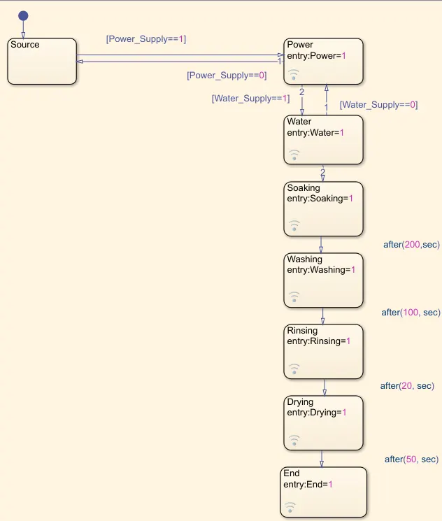
Control logic is model system logic using state machines, flowchart and truth tables. Stateflow is a Simulink tool to implement state machine.
Output:
Case 1: When the power is 0 and power supply is not available. The system remains inactive
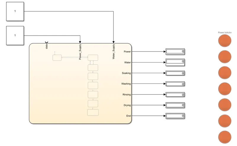
Case 2: When the power is 1, water is 0 and power supply is turned on. Since there is no water the system remains inactive
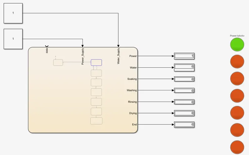
Case 3: When the power is 1, water is 1 and power supply is turned on. Since there is water available the system will run.
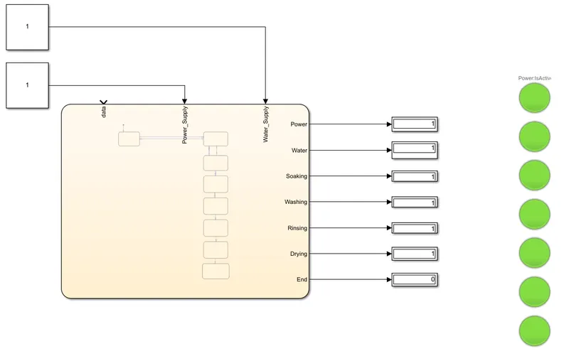
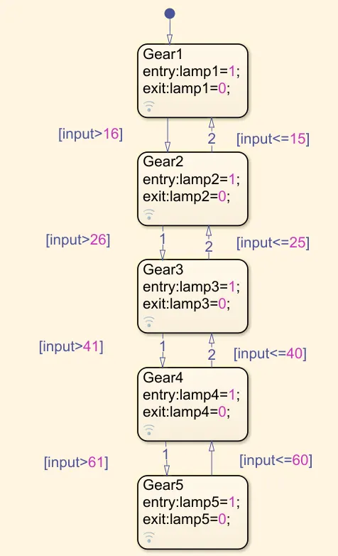
Q: Make a Simulink chart for the “Gear shift” logic as per below conditions:
Speed Range(kmph) Gear
0 to 15 1
16 to 25 2
26 to 40 3
41 to 60 4
Above 61 5
Give speed input while the simulation is running & display the gear number.
Gear shift mechanism: The Gear-shift Mechanism which shifts gears is usually located in the gearbox cover and is driven by a rocker lever. For example, in the gearbox Gear-shift mechanism of a truck, the lever 51 mounted directly on the gearbox swings freely in the spherical socket of the gearbox cover, resting on it with a ball-shaped bulge. The lever is held by a spring and a clamp 50. The lower end of the lever 51 enters in the groove of one of the forks mounted on the sliders 54 and 55. The gear lever is provided to the operator, who has the control of the system. There is swivel pin at the lower end of the gear shifting lever. This swivel pin moves within the box shaped cavity provided at the selector rod jaws.
Control logic of gear shift
Output
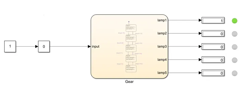
Case 1: When the speed is given 0km/hr from the slider gain. The gear is shifted to Gear 1.
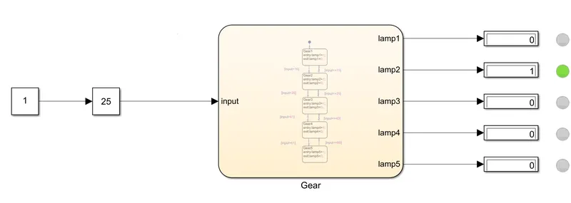
Case 2: When the speed is given 25km/hr from the slider gain. The gear is shifted to Gear 2.
Case 3: When the speed is given above 60km/hr from the slider gain. The gear is shifted to Gear 5.
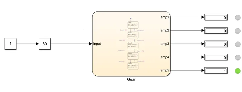
Likewise changing the speed from the slider gain the gear position will change.