Week-7 Challenge: DC Motor Control
1. Speed control of a DC motor using BJT H-bridge
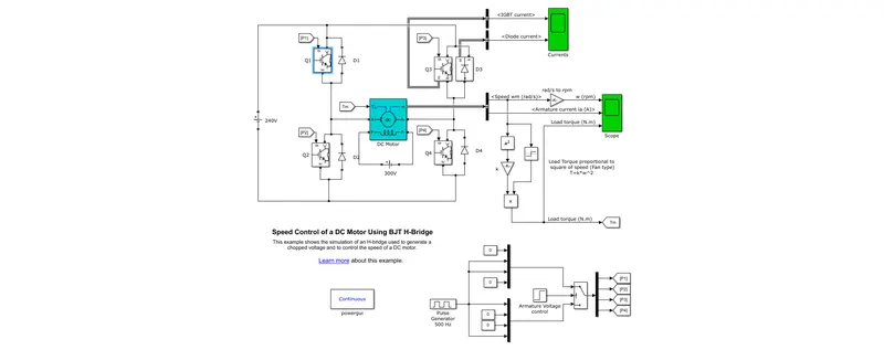
Figure showing below is a MATLAB Model of BJT H-bridge Speed Control circuit of a DC Motor.
A. The H-bridge is made up of four IGBT/Diode pairs. Q1 and Q4 or Q2 and Q3 transistors are switched at the same time. When Q1 and Q4 are turned ON, a positive voltage is given to the motor, and when Q1 and Q4 are turned OFF, diodes D2 and D3 work as free-wheeling diodes. When Q2 and Q3 are turned ON, a negative voltage is given to the motor, and when they are turned OFF, diodes D1 and D4 work as free-wheeling diodes. A 5 HP 240V 1750 rpm DC Motor block is used in the circuit. In the field 300V is applied. Load Torque calculated from the rotational speed is fed to the DC motor block as the mechanical torque input.
500Hz Pulse Generator given for trigeering the IGBTs with 75% duty ratio. Armature Voltage control is given with a step size of 0.5 sec. Which means Motor will rotate in clockwise direction for 0.5 seconds (IGBT 1&4: ON, IGBT 2&3: OFF) and anti-clockwise direction for another 0.5 seconds (IGBT 1&4: ON, IGBT 2&3: OFF). During the ON time of 0.5 seconds, each IGBT will be triggered ON & OFF for 250 times with a duration of 0.002 seconds (ON for 0.0015 sec and OFF for 0.0005 sec).
B. Armature current shoot-up
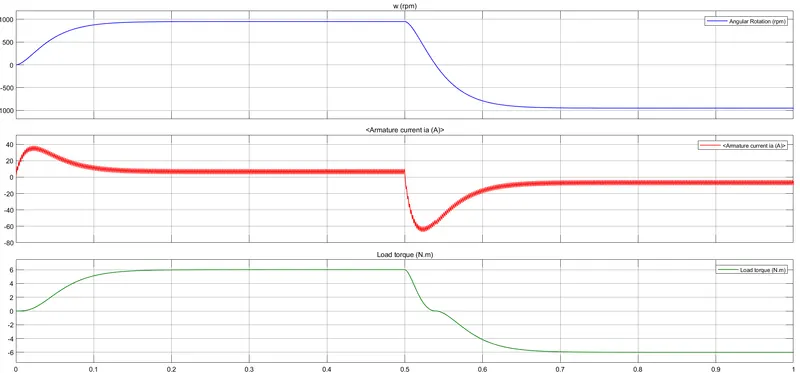
IGBTs are controlled with a 500Hz pulse generator with the given Duty ratio of 75%. So, the Voltage input to the motor will be 240x75% = 180V. Intitially when starting, there will be rise in armature volatge will lead to increase in armature current and settle down to normal. Low temperature and thus low armature resistance can be factors for this. This armature current shoot up will be more if the armature voltage is increased and less for lower voltage. This can be checked by varying the duty ratio. Armature current for the set duty ratio of 75% is shown below.
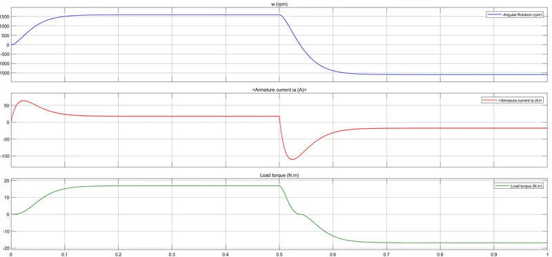
Duty ratio set to 99% and the obtained armature current is shown below. Which is higher compared to 75%.
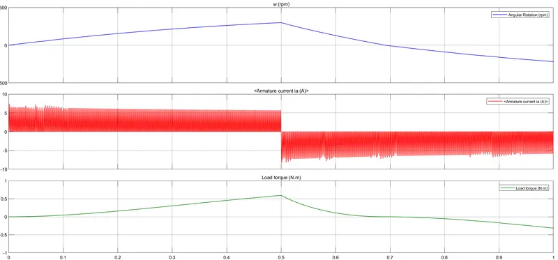
Duty ratio set to 40%. Here we could see that the current shootup is feeble.
C. The Four-Quadrant Chopper DC Drive (DC7) block and H-bridge model.
Below showing is the The Four-Quadrant Chopper DC Drive (DC7) block
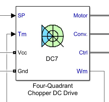
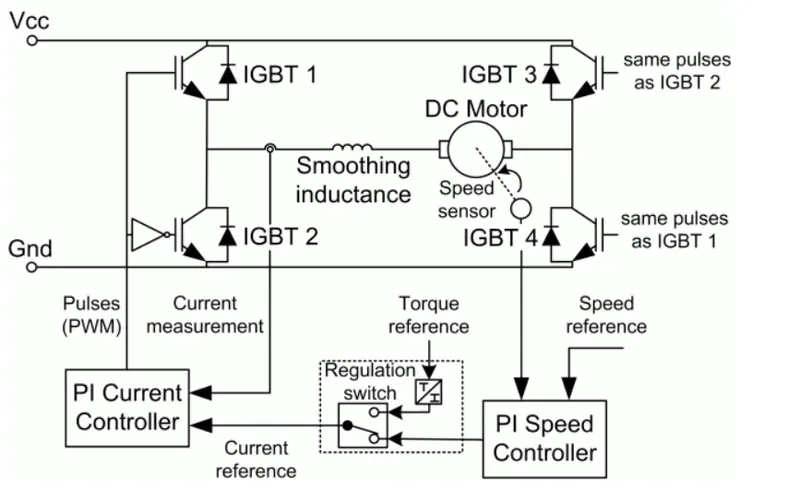
The block is made of the below showing basic simulink blocks such as chopper circuit using IGBT, PI Speed COntroller, Current Controller and Regulation Switch. Specifications of DC machine, Converter, and Controller can be given to a single individual. That is a major difference between H bridge. In H bridge separate DC motor block has to be added to load side. IGBT triggering circuits and Voltage control circuits need to be created separately.
| Specifications | DC 7 DC Drive | H Bridge Model |
| Speed controlled |
varying current pulses from PI current controller |
varying duty cycles voltages |
| Regenerative breaking | Occurs | occured by changing polarity of current flow |
| Smooth Inductance | Present | Not present |
| Mode of Operation | Discrete | Continuous |
2. 2-quadrant chopper using simulink
A 2 quadrant chopper developed from the H bridge circuit as shown below.
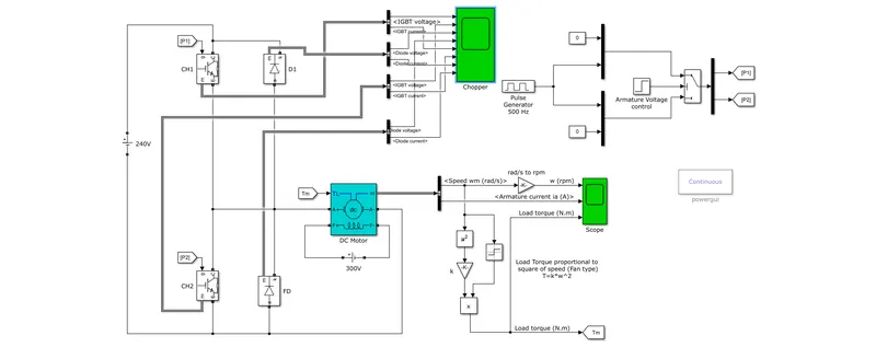
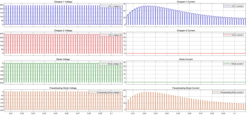
It consists of two IGBTs CH-1 and CH-2. Then a Diode D2 and Freewheeling Diode. First quadrant operation is Motoring where, when CH-1 is ON, Current flows from Source to load hence there will be a positive output voltage. When CH-1 is OFF, Energy stored by the inductive load circulates through the freewheeling diode and making the current direction and voltage of the same polarity.
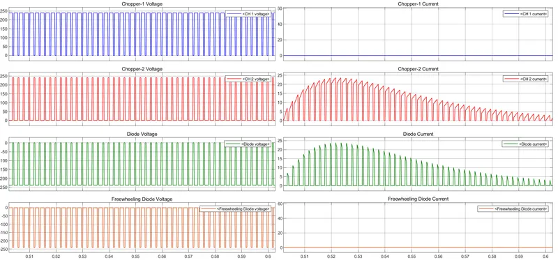
Second quadrant operation is Regeneration. During regeneration, motor acts as generator and generated power supplied to source. When CH-2 is ON, current from motor circulates through CH-2 and when CH-2 is OFF, generated current flows to source through Diode-1.
The output result obtained is shown below.
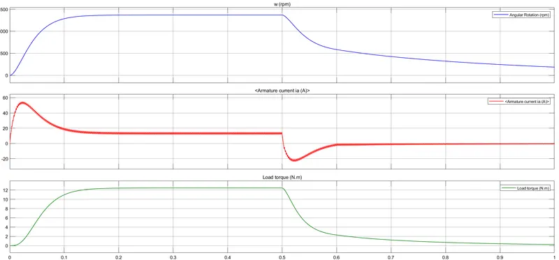
Voltages and Currents of IGBTs and Diodes during the first quadrant or Motor operation are shown below. Current is there for Ch-1 and Freewheeling diode and that for CH-2 and Diode-1 is zero.
Voltages and Currents of IGBTs and Diodes during the second quadrant or Regeneration operation are shown below. Current is there for Ch-2 and Diode-1 and that for CH-1 and Freewheeling Diode is zero.
3. BLDC motor
A brushless DC motor, also referred to as a BLDC, is a permanent magnet synchronous electric motor that runs on direct current (DC) power and employs an electronically controlled commutation system in place of a mechanical one. Commutation is the process of generating rotational torque in the motor by varying the phase currents through it at the proper times. Trapezoidal permanent magnet motors are another name for BLDC motors.
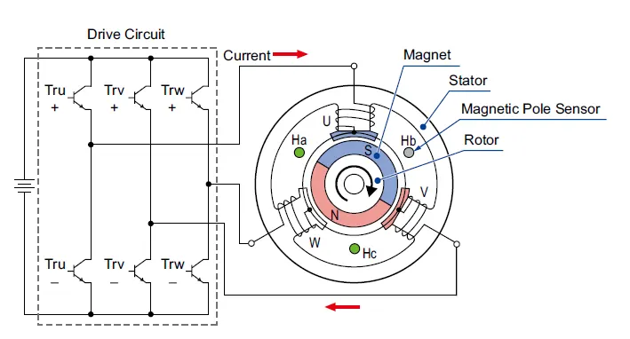
A permanent magnet rotor and a stator with a series of coils make up a BLDC motor, which uses electrical commutation. The armature is fixed and the motor field rotates in this. Transistors or silicon-controlled rectifiers electronically switch the armature coils at the proper rotor position such that the armature field is in space quadrature with the rotor field poles. As a result, the rotor rotates due to the force imposed on it. The most popular devices for detecting the position of the rotor are hall sensors, which are installed all around the stator. When to switch the armature current is guided by the sensor's response on the rotor position.
Construction
Stator: A BLDC motor's stator is comprised of layered steel laminations that carry the windings. These windings are installed in slots cut axially along the stator's inner circumference. These windings can be organized in either a star or a delta configuration. Most BLDC motors, however, feature a three-phase star-connected stator.
Rotor: The rotor of a BLDC motor contains a permanent magnet. Depending on the application, the number of poles in the rotor might range from 2 to 8 pole pairs with alternate south and north poles. The flux density of the material should be high in order to obtain maximal torque in the motor. A suitable magnetic material for the rotor is required to generate the appropriate magnetic field density.
Hall effect Sensor: The information provided by the Hall sensor is used to synchronise stator armature excitation with rotor position. Because BLDC motor commutation is regulated electronically, the stator windings must be activated in sequence in order to rotate the motor. Before activating a certain stator winding, the rotor position must be recognised. As a result, the rotor position is sensed by the Hall Effect sensor integrated in the stator.
Advantages
- It lacks a mechanical commutator and the accompanying issues.
- The usage of a permanent magnet rotor results in high efficiency.
- Due to the lack of brushes that limit the pace, the operation is fast even when loaded and unloaded.
- Motor geometry is smaller and lighter than brushed DC and induction AC motors.
- The commutator system has a long life since it does not require inspection or maintenance.
- Because of the stator's low inertia and carrying windings, it has a higher dynamic responsiveness.
- There is less electromagnetic interference.
- Due to the lack of brushes, the operation is quiet (or low noise).
Disadvantages
- These motors cost a lot.
- Pricey electronic controller needed to control this motor.
- Few availabitity of integrated electronic control solutions particularly for small BLDC motors.
- Requires sophisticated driving electronics.
- Need for more sensors