Project 1 (Mini Project on Vehicle Direction Detection
Aim of the Project
Aim is to create a MATLAB Simulink model with the given details for Vehicle Direction Indicator.
Description
Vehicle Direction Indication is one of the features of ADAS. As the specificatios given, Vehicle Direction is Indicated sensing the angular movement of the Steering Wheel as well as the Road sign data stored by the Camera Sensor.
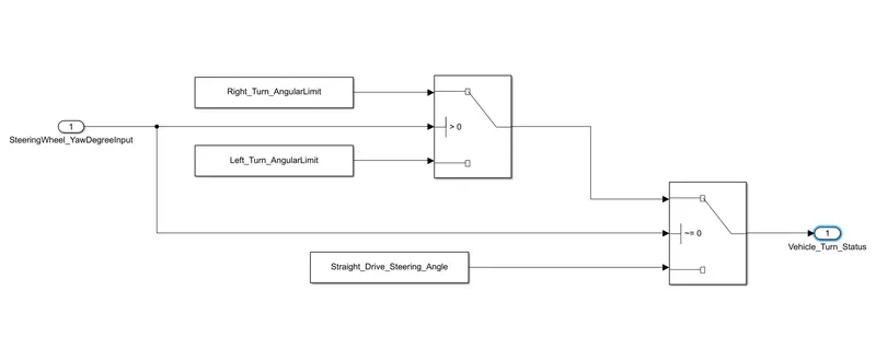
The system is divided into two parts. In one part, direction of vehicle is assessed by comparing the steering wheel movement with the predefined angular limits. As we know if the steering angle is zero then its straight drive. If it is greater than zero then Right Turn. If its less than zero then Left Turn.
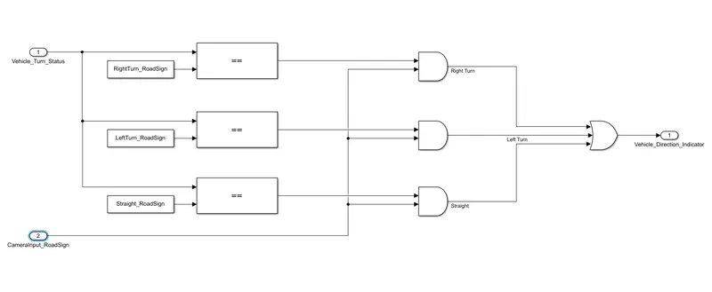
In the second part the result from the first part is compared with the camera sensed data and given as Vehicle Direction Indicator.
Simulink Model
Below showing figure is the Simulink Model created as per the specification. It contains two input Steeringwheel_YawDegreeInput and CameraInput_RoadSign. and an output Vehicle_Direction_Indicator
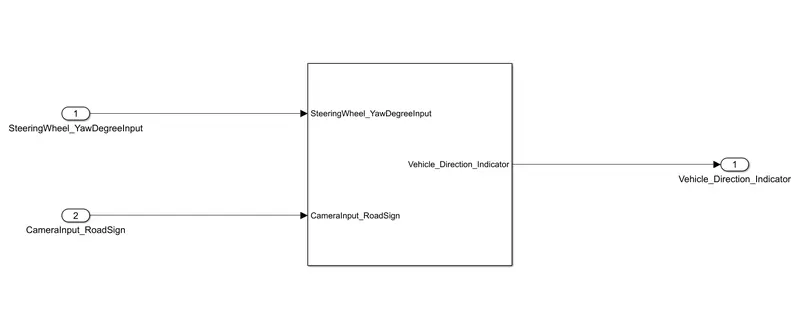
Inside Subsystem:
Two Subsystems: Requirement 1 & 2
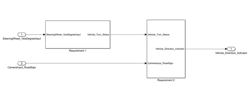
Subsystem Requirement- 1 is shown below. Here the Steeringwheel_YawDegreeInput is given as input where a logic is created to give the output Vehicle_Turn_Status. Predefined values are there for Right_Turn_AngularLimit, Left_Turn_AngularLimit, and Straight_Drive_Steering_Angle. If the Steeringwheel_YawDegreeInput is is zero then its Straight_Drive_Steering_Angle. If it is greater than zero then Right_Turn_AngularLimit. If its less than zero then Left_Turn_AngularLimit.
Subsystem Requirement- 2 is shown below. Vehicle_Turn_Status will be Right_Turn_AngularLimit or Left_Turn_AngularLimit or Straight_Drive_Steering_Angle. Which is then compared with the camera sensed RightTurn_RoadSign, LeftTurn_RoadSign, Straight_RoadSign.
Data Dictionary
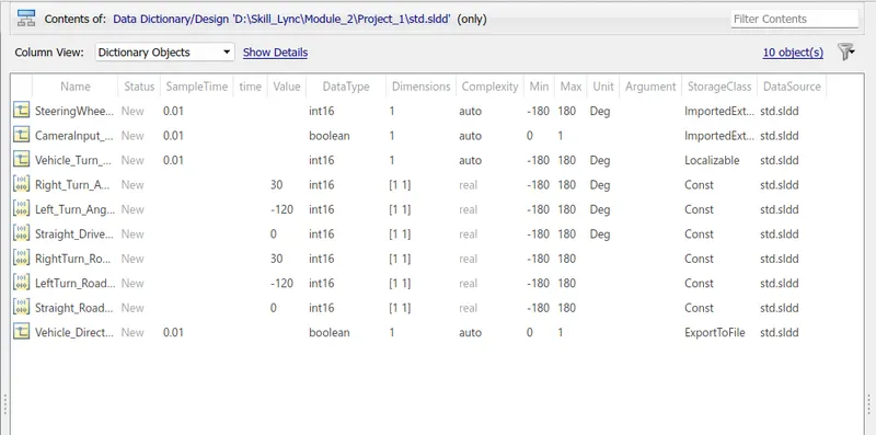
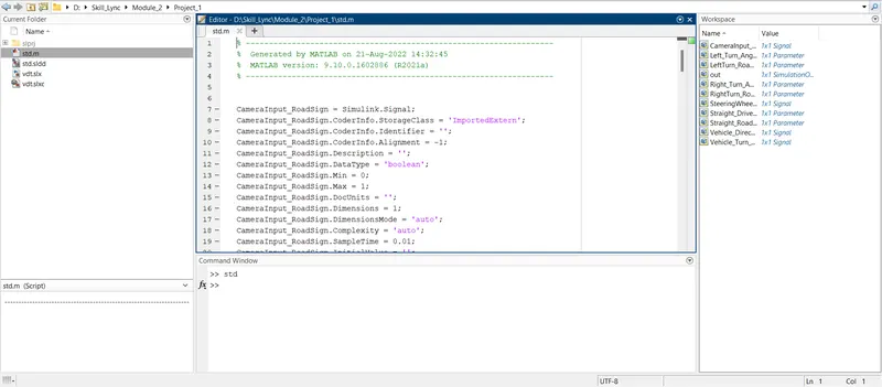
SLDD created is exported to file and RUN to create the workspace as shown below.
Result & Conclusion
Simulink Model for Vehicle Direction Indicator is developed with the given specifications. Two subsystems included based on two requirements. SLDD created and loaded to workspace. More data required for clear modelling of the system.
In the model created as per the specification:
- If the SteeringWheel_YawDegreeInput is set to Greater than zero, Vehicle_Turn_Status will be Right Turn Angular Limit
- If the SteeringWheel_YawDegreeInput is set to zero, Vehicle_Turn_Status will be Straight_Drive_Angle
- If the SteeringWheel_YawDegreeInput is set to Less than zero, Vehicle_Turn_Status will be Left Turn Angular Limit
- If the CameraInput_RoadSign is zero, Vehicle_Direction_Indicator will be zero for any condition
- If the CameraInput_RoadSign is one, Vehicle_Direction_Indicator will be one for any condition and the condition can be assesed from the Vehicle_Turn_Status value.