Week -2
1. Simulink model of Doorbell using solenoid block
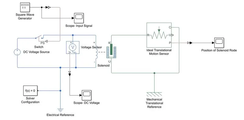
The figure shown below is the MATLAB model created for Door Bell using Solenoid Block.
Steps involved in developing and simulating the model is as follows:
- A DC supply is connected to the solenoid block through a switch.
- 50V DC Voltage supply is connected as per the specification of Solenoid Block.
- While applying electrical supply, solenoid rod moves towards C and remains there. After disconnecting electrical supply, Rod moves back to R.
- Movement of the solenoid is viewed in scope through a translational motion sensor.
- A square pulse with amplitudes -1 to +1 with a period of 4 seconds as shown in below figure is given to the switch.
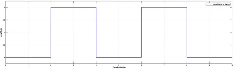
- Threshold voltage of Switch is 0V. Switch will be turned ON and OFF both for a 2 second time. That is, Supply will be provided to solenoid for 2 seconds only and not for another 2 seconds as shown in the below image.
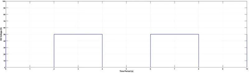
- Since supply is turned ON and OFF for altternating 2 seconds, Solenoid rod will move towards C and and back to R in each seconds as shown in the below image. Rod moves for a distance of 5mm which also can seen in the picture.
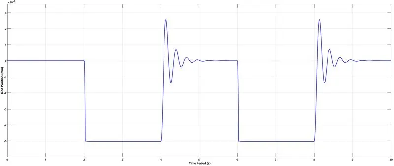
In order to return back the rod to the initial position, some damping values have to be given.
2. Thermistor to sense the temperature of a heater & turn ON or turn OFF the fan as per the given conditions
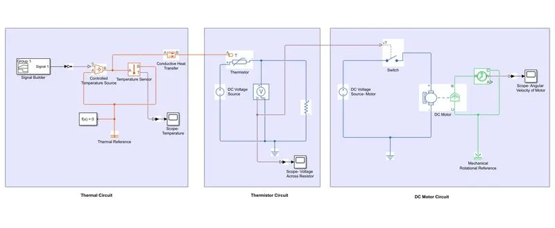
The figure shown below is the MATLAB model created for a Temperature controlled Fan using Thermistor.
Steps involved in developing and simulating the model is as follows:
- An electric circuit for DC motor is created with DC supply and switch. DC motor represents Fan in this model.
- A Rotational sensor is connected to motor and its output is then connected to a scope to view the operation of motor.
- Turn ON and OFF of motor depends on the signal coming to the switch connected in DC motor circuit and the pattern of signal depends on the operation of thermistor circuit.
- Thermistor varies its resistance value according to the variation of temperature of heat affecting on it.
- Heating of thermistor is created by connecting a heat transfer block with a purticular temperature value.
- Temperature of the heat flow is determined by the inputs of the temperature source.
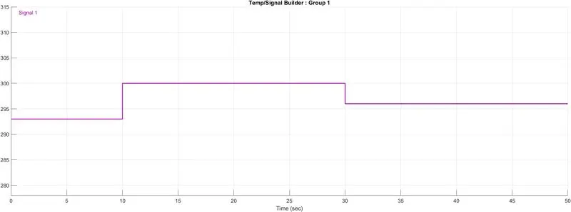
- The condition for the simulations are, for a total period of 50 seconds, temperature in the first 10 seconds should be 20°C followed by 27°C from 10sec to 30sec and 27°C from 30sec to 50sec.
- One of the input of the temperature source is zero or reference and the other input is the temperature values as per the condition in Kelvin since all the parameters in blocks of thermal circuits are in Kelvin.
- Signal builder is used for creating signal in temperature values of specified conditions as shown below.
- As per the given signal, the temperature output of the temperature source is as shown below.
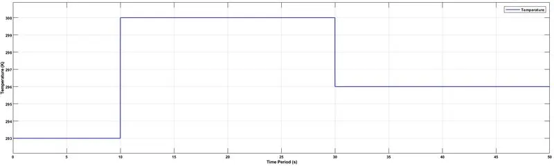
- Thermistor is heated using heat transfer block with temperature values varying with time as per the temperature source.
- Voltage across resistor connected in the thermistor circuit varies as shown below according to the thermistor resistance due to heating and cooling of thermistor.
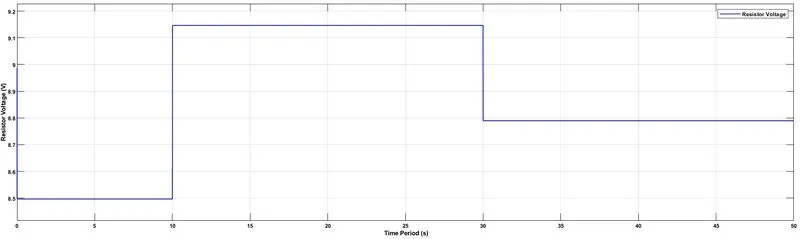
- This voltage is given to operate the switch in the DC motor circuit. Fan must be turned ON whenever the temperature goes above 25°C. The resistor voltage corresponding to the temperature of 25°C is 8.9V. Hence, the threshold voltage of switch set to 8.9V so that whenever the resistor voltage goes above 8.9V, the Fan or Motor turns ON and when the voltage goes below 8.9V, motor turns OFF.
- Voltage above 8.9V means temperature is above 25°C and vice versa.
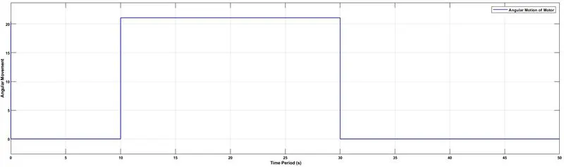
- From the said condition, Motor will be turned ON during 10sec to 30sec as seen in the below figure.