Week-7 Challenge: DC Motor Control
1.a b & c.Speed contrl of a DC motor using BJT H-bridge, scope result of armature & the Four-Quadrant Chopper DC Drive (DC7) block comparison with BJT H-bridge:
Circuit diagram:
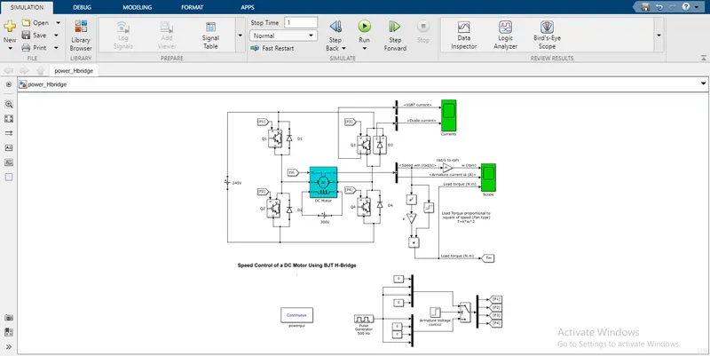
- BJT is known as Bipolar Junction Transistor which is used in DC Motor.
- This BJT is a type of switch used in the power electronics.
- There is 240V batter pack and it has 2 terminals, positive terminal is connected to the P1 & P3 switch then negative terminal is connected to the P2 & P4 switches.
- DC motor is at centre of the 4 switches.
- BJT switches has 2 signals ,one is control signal which is in left side and other side there is a power signal.
- Control signal has base terminal and power signal has collector terminal and emmitor terminal.
- And it has a diode with each and every switch to return the current if the switch is in off condition.
- Opperation of the switches should be done fast if not the shortcircuit may occur.
- And the switching opperation should not be done by direct opperation like P1 & P2.
- Because it is connected directly,so flow of the resistance may be low and short circuit may occur.
- Voltage supply from the battery should passed through P1 & P4 switches.
- When the voltage enters the P1 switch it will be on and the current will be flowed to the motor.
- The motor get energised and starts rotating in the forward direction & the current flows to the P4 switch to the negative.
- When the P1 & P4 switch is in off state, the current flows through the P3 & P4 switches.
- When the current flows through these switches, motor starts to rotate in the backward direction.
- For forward direction current flows through Q1D4 & Q4D1.
- For reverse direction current flows through Q3D2 & Q2D3.
Graph:
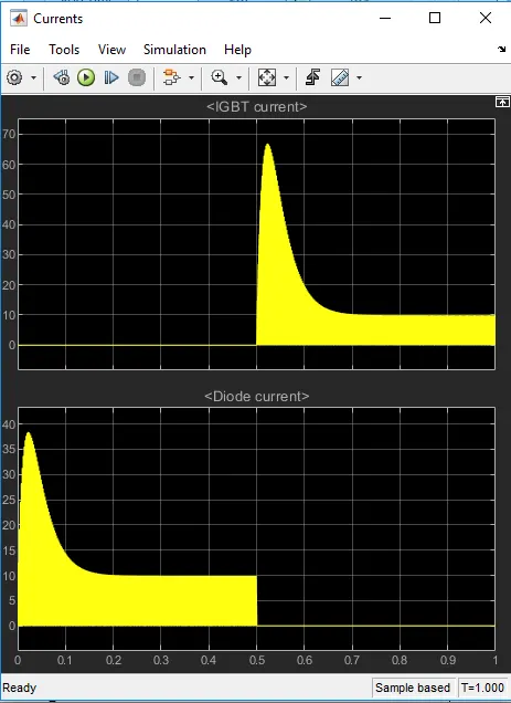
This graph indicates the output of IGBT current and diode current.
b.Armature current
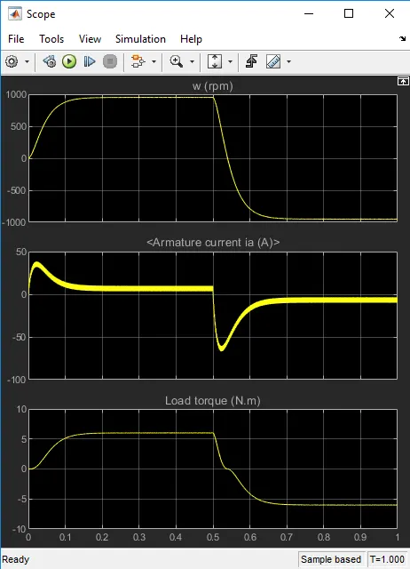
This graph indicates the output of speed,armature current & load torque.
- Armature current is 0 at its initial stage.
- When the motor is energised and rotates at the forward direction.
- The peak point is at 45A & falls down by 10A,remains constant till 0.5 seconds.
- When the motor is energised and rotates at the reverse direction.
- The peak point is at around -65A & raises to 10A & remains constant till 1 second.
c.Four-Quadrant Chopper DC Drive (DC7) block comparison with BJT H-bridge:
Circuit diagram
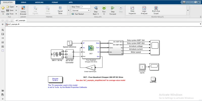
- Four quadrant chopper is completly different comppared to the BJT H-bridge.
- Three phase supply source is connected to the AC to DC converter.
- AC to DC converter is connected to the four quadrant chopper block.
- Four quadrant chopper has 4 switches and diodes to opperate the dc motor.
- These switces are opperated multi times per second.
- If the current flows in the same direction of the switches like CH1 & CH2.
- Short circuit will be occured in the process.
- Current flow should be with CH1,CH4 & CH2,CH3.
- If the curent flows in this path of opperation,the process of the motor will be good.
- If not short circuit may occur.
- In DC drive block motor speed and motor torque is connected by load torque.
- Insulated gate bipolar transistor (IGBT) switches are used in this 4 quadrant chopper dc drive.
- Motor speed,armature voltage and current are measured.
Graph:
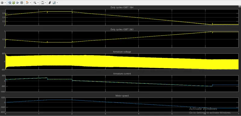
- Armature voltage passes high voltage to the motor.
- Duty cycle IGBT increases gradually to 0.6 and again raises about 0.65 till 2 seconds and slides to the initial condition.
- Armature current raises around 250 and falls to the negative form around -400A.
- Motor speed is increased aroud 500 rpm and the speed is decreased to -1250 rpm at 7 seconds final time.
2. Two quadrant chopper using simulink:
Circuit diagram:
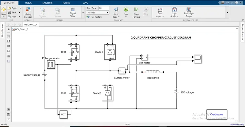
- Battery is upto 48 volts.
- Positive terminal of the battery is connected to the switch 1 and diode 1.
- Negative terminal is connected to the switch 2 and diode 2.
- Mosfet switches are used in this 2 quadrant chopper.
- Current meter is used to measure the current reading.
- Volt meter is usd to measure the volt reading.
- Inductane and DC voltage supply is connected for the load.
- CH1 & D2 is for acceleration.
- CH2 & D1 is for breaking force.
- When the acceleration is applied power is taken from the battery source to the motor through CH1.
- If CH1 is in off state the power is transfered through D2 to the motor.
- When the breaking is applied to the motor the battery gets charged,it is known as regenerative breaking force.
- When the breaking is applied to the motor CH2 will be on.
- If CH2 is in off state,sorce will be travelled through D1 and it reaches the battery power.
- So the battery will get charge when the brake is applied.
GARPH:
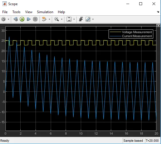
Current passes through the negative and to possitive.
Voltage has the constant flow.
3.Operation of BLDC Motor?
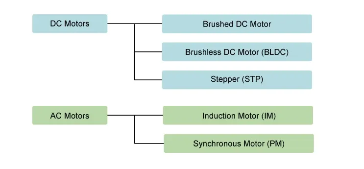
Types of motors:
Construction of BLDC motor:
- In Brushless DC Motor (BLDC) commutator & brushes are eliminated.
- So inverter or circuit switches are integrated to produce unidirectional torque by the motor.
- So sometimes it is also called as Electronically Commutated motors.
- A BLDC motor also consists of two main parts a stator and a rotor.
- Permanent magnets are mounted on the rotor of a BLDC motor and the stator is wound for a specific number of poles.
- Also a control circuit is connected to the stator winding.
- This is the basic construction of brushless motor.
BLDC Motor:
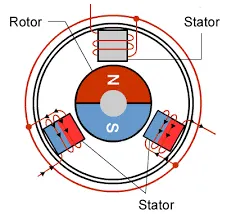
There are 2 types of BLDC motors:
- Inner rotor design
- Outer rotor design
Working of BLDC motor:
- Brushless dc motors donot have brushes and commutator.
- The coils are not located on the rotor.
- The rotor is a permanent magnet, the coils do not rotate.
- But it is fixed in place on the stator.
- Because the coils do not move, there is no need for brushes and a commutator.
- With the brushed motor, rotation is achieved by controlling the magnetic fields generated by the coils on the rotor.
- While the magnetic field generated by the stationary magnets remains fixed.
- To change the rotation speed, want to change the voltage for the coils.
- In a BLDC motor, it is the permanent magnet that rotates, rotation is achieved by changing the direction of the magnetic fields generated by the surrounding stationary coils.
- To control the rotation adjust the magnitude and direction of the current into these coils.
- A BLDC motor with three coils on the stator will have six electrical wires extending from these coils.
- Three of these wires will be connected internally, with the three remaining wires extending from the motor body.
- Wiring in the BLDC motor is more complicated than simply connecting the power cell’s positive and negative terminals.
Advantages of BLDC Motor:
- Output power of up to 660 watts
- Incredible longevity
- Compact size
- High speed and high efficiency