Project - Speed Control of a Direct Current (DC) motor
SIMULINK PROJECT
DC MOTOR USING PID CONTROLLER
INTRODUCTION
- Direct current machines are the most versatile energy
conversion devices. Their outstanding advantage is that the
volt-ampere or speed torque characteristic of these machines
are very much flexible and easily adaptable for both steady
state and dynamic operations. When a wide range of speed
control and torque output are required dc motor is an obvious
choice[1]. - The state space approach is a generalized time domain
method for modeling, analyzing and designing a wide range
of control systems and is particularly well suited to digital
computational technique. In this paper armature current and
speed of the dc motor are taken as state variables.
In this section we shall present a design method commonly
called pole-placement technique. It will be shown that if the
system considered is completely state controllable then poles
of the closed loop system may be placed at the desired
location with the help of state feedback gain matrix K. - In pole-placement approach to the design of control system
we assumed that all state variables are available for feedback.
In practice however all state variables are not available for
feedback. So it is necessary to estimate unavailable state
variables. Estimation of unmeasurable state variable is
commonly called observation.
DC MOTOR SIMULATION USING MATLAB
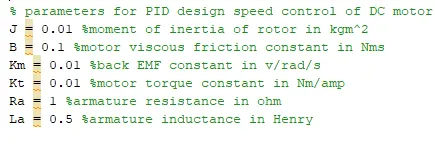
Parameters
Block Diagram
- Voltage supply = 230volts
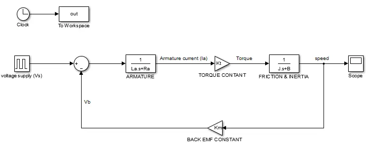
- Voltage supply (Vs) is generated by the values of volts.
- And then voltage is passed to the armature block , which has armature inductance (La) & armeture resistance(Ra).
- And then armature current (Ia) is passed towards the torque constant which is (Kt).
- Now the torque goes to the friction & inertia block which is J & B.
- And now the speed will be the output of the DC motor which is out from friction & inertia block.
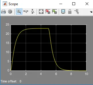
- Output of the DC motor is presented.
GRAPH OF DC MOTOR:
DC MOTOR USING PID CONTROLER
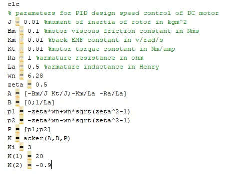
Parameters of PID controler:
Block diagram :
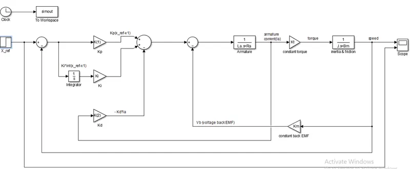
- In this PID controler step block is used for the input value.
- Step block is known as X_reference block.
- In this PID controler there are 3 gain blocks, which is Kp, Ki & Kd.
- Kp gain block is known as constant proprotional.
- Ki gain block is known as constant integrator.
- Kd gain block is known as constant derivative.
- Input value and the speed of the motor is summed by the summing block.
- Then the input is passed to the Kp gain block, which has the value as 0.
- Ki is multiplied with the integrator and integrator is connected with the X_reference output.
- And now Kd is paired with the Armature current (Ia).
- Atlast Kp, Ki & Kd ouyput is met in the summing junction.
- Finally PID controller output is connected with the DC motor.
working prionciple:
- A PID controller produces an output signal consisting of three terms- one proportional to error signal, another one proportional to integral of error signal and third one proportional to the derivative of the error signal.
- The proportional controller stabilizes the gain but produces a steady state error.
- A PID controller can be used to regulate the speed of an electric motor, the position of a robot arm, or the temperature of a furnace.
- X_reference (X_ref) is the measured or sensed value of the controlled process.
- The X_ref is input to the PID controller to calculate the error.
Graph of PID control DC motor:
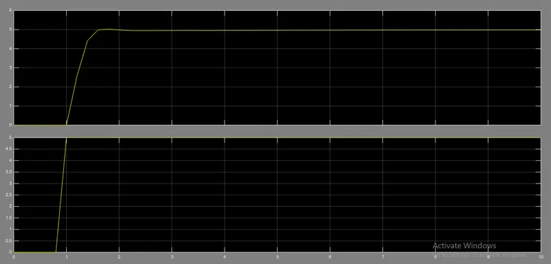
- This graph represents the output of DC motor using PID control.
- Settling time is on 2sec.
- And there is no overshoot.