Week-7 Challenge: DC Motor Control
TASK I
a).Speed control of a DC motor using BJT H-bridge
When used in power switching applications, the bipolar junction transistor (BJT) functions as an IGBT. A forward voltage Vf is created between the collector and emitter when it is conducting (BJT working in the saturated zone) (in the range of 1 V). Therefore, it is possible to represent the BJT device using the IGBT block. The gate current controlling the BJT or IGBT is not simulated by the IGBT block.A Simulink signal (1/0) controls the switch. The pre-set model is utilised by the DC motor (5 HP 240V 1750 rpm). It simulates the load of a fan -Load torque is proportional to square of speed. When the duty cycle (given in the Pulse Generator block) is changed from 0 to 100%, the armatures mean voltage can be changed from 0 to 240 V.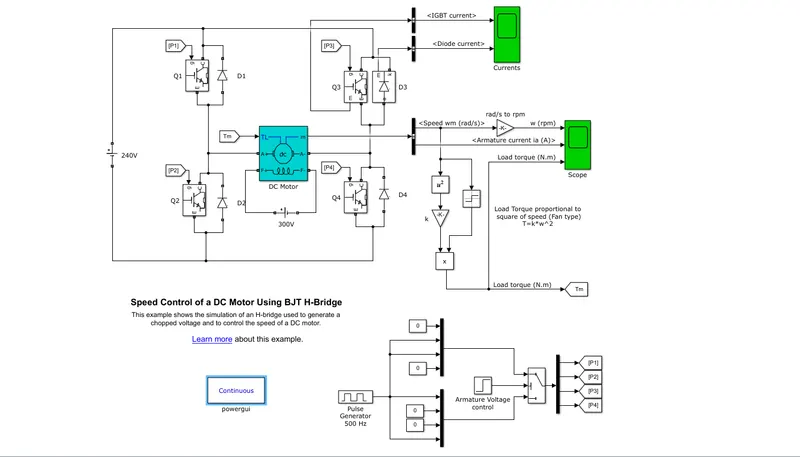
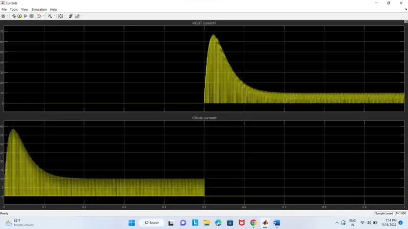
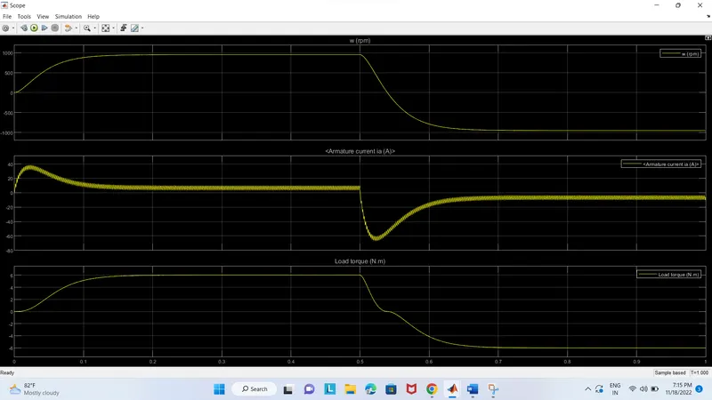
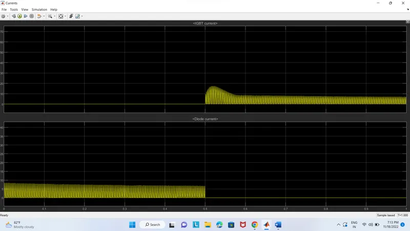
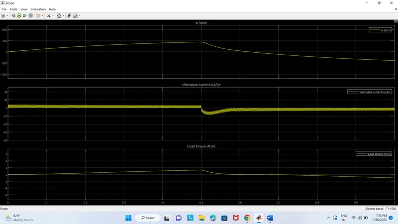
There are four BJTpairs on the H Bridge. The simultaneous switching of two transistors. When Q1 and Q4 are switched off, a positive voltage is provided to the monitor diodes D2-D3, which then function as freewheeling diodes. A negative voltage is given to the motor when Q2 and Q3 are fired, and when Q2 and Q3 are turned off, diodes D1 through D4 work as freewheeling diodes. The motor starts with a 75% duty cycle and moves in the positive direction (mean DC voltage of 180V). When the armature voltage abruptly reverses at time t = 0.5 seconds, the motor starts to rotate in the opposite direction. The scope block displays the motor speed, armature current, load torque, and current flow in the BJT Q3 and diode D3 components.
The motor starts with a 75% duty cycle and moves in the positive direction (mean DC voltage of 180V). The armature voltage suddenly changes at time t=0.5 seconds, causing the motor to run in the other direction. Scope displays the currents flowing in the BJT Q3 and the diode D3 as well as the motor speed, armature current, and load torque.
b). armature current shoot-up -50% pulse width (percent of period)
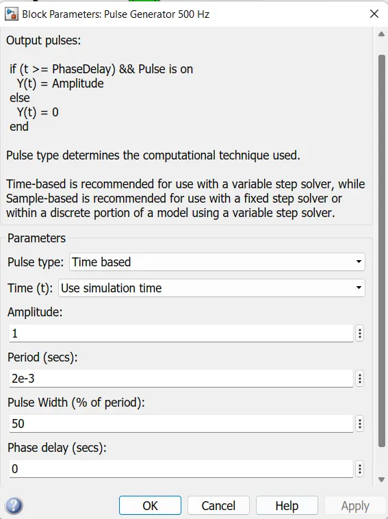
Therefore, as pulse width gets smaller, the DC motor's applied voltage gets smaller as well, which in turn causes the armature current to decrease.
c). BJT H-Bridge and Four Quadrant Chopper Comparison
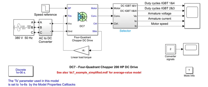
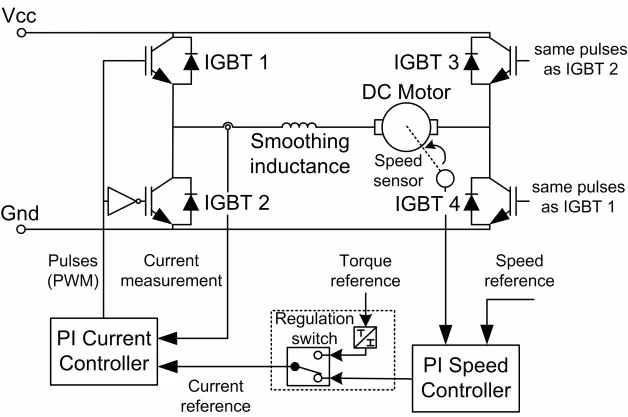
A four-quadrant DC-supplied chopper drive for DC motors, also known as a DC-DC PWM converter, is represented by the Four-Quadrant Chopper DC Drive (DC7) block. This drive has four-quadrant operation and closed-loop speed regulation. The machine's reference armature current is output by the speed control loop. The chopper duty cycle matching to the commanded armature current is determined using a PI current controller. To get the necessary PWM signals for the chopper, this duty cycle is then contrasted with a sawtooth carrier signal.
BJT H-Bridge
- It runs in two quadrants: forward and backward motion.
- The polarity of the current is altered to vary the motor's direction of rotation.
- Low switching frequency results in armature current shoot-up.
- H-bridge circuits are used in robotics technology.
- Regenerative braking is not possible.
- The H-Bridge circuit's use as a motor driver circuit is its most significant application.
- H-bridge circuits can fit in small places
Four Quadrant chopper
- The four quadrant chopper DC drive, which consists of four quadrants including forward motoring, forward regenerative braking, reverse motoring, and reverse regenerative braking, distributes the necessary current supply for each sector.
- There is little maintenance and good efficiency.
- Widely utilized in automobiles.
- It is feasible to engage in regenerative braking.
- Four-quadrant choppers are typically small and light.
- Due to the high switching frequency of DC-DC coverters, armature current ripple is reduced.
TASK II
2-quadrant chopper using simulink
CHOPPER- A dc-to-dc converter, commonly referred to as a "dc chopper," is a static device that converts a constant dc voltage source into a variable dc voltage. Trolley cars, battery-powered vehicles, traction motor control, large-scale dc motor control, etc. all frequently use choppers. Additionally, they serve as dc voltage regulators. There are two different kinds of choppers: step-down choppers and step-up choppers. The output voltage of step-down choppers will be lower than the input voltage, whereas the output voltage of step-up choppers will be higher than the input voltage.
Case I
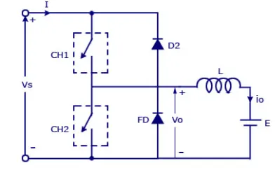
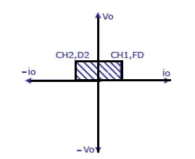
When chopper CH1 is turned ON, source Vs is connected directly to the load, making source voltage and load voltage the same. According to the circuit schematic, which is assuming a positive voltage, the direction of load current is from source to load. The free-wheeling diode (FD) enters the circuit when CH1 is switched OFF because it becomes forward biassed and shorts the load. The output voltage Vo therefore drops to zero. However, as indicated in the circuit diagram, the io continues to decline through the FD and L in the same manner. The action of the chopper is therefore in the first quadrant as a result of the average output voltage Vo and current Io being positive.
Case II
When chopper CH2 is turned ON, load DC source E sends current through CH2 and the load. Since the direction of this current io will be opposite to what is depicted in the circuit diagram, it is believed to be negative. Vo, the output voltage, is at zero at this moment. Diode D2 becomes forward biassed when CH2 is turned off, which causes the current from the load to enter the source. When the chopper CH2 is turned off, the load is linked to the source via D2, resulting in an output voltage of Vs at this point. As a result, the load current is always negative, meaning that the chopper is operating within the second quadrant.
The average voltage in this sort of Chopper will always be positive, while the average load current may be either positive or negative. It is not advisable to turn on the two switches CH1 and CH2 at the same time since the combined action could result in a short circuit in the supply lines. These kinds of chopper configurations are employed for regenerative braking and motoring.
The main advantages of this drive over other DC drives are its speed of implementation and ability to function in two quadrants (forward motoring and reverse regeneration). Additionally, compared to thyristor-based DC drives, a smaller armature current ripple is obtained because to the employment of high switching frequency DC-DC converters. However, for all two-quadrant DC drives, reversible and regenerative operations (reverse motoring and forward regeneration), which are required in most DC drives, cannot be obtained.
Model
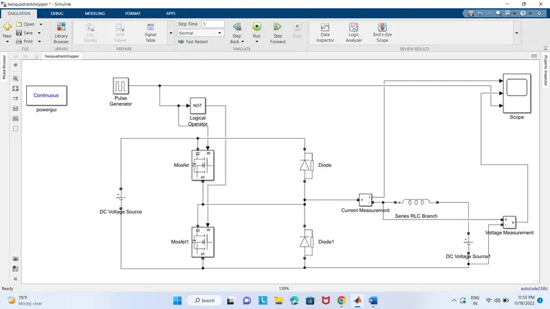
The following blocks are used to develope the model
- Power gui
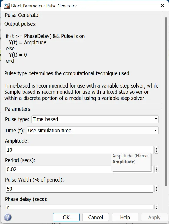
- Pulse generator
- Logical operator
- Mosfet
- Diode
- Current measurement
- Voltage measurement
- Series RLC with inductor only
- Dc source
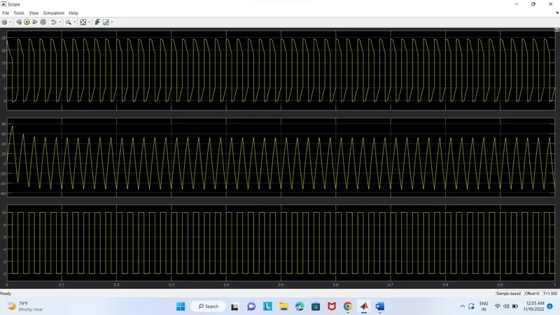
Scope Result
TASK III
BRUSHLESS DC MOTOR (BLDC)
A brushless DC electric motor (BLDC motor or BL motor), also known as an electronically commutated motor (ECM or EC motor) or synchronous DC motor, is a synchronous motor using a direct current (DC) electric power supply. It uses an electronic closed looped controller to switch DC currents to the motor windings producing magnetic fields which effectively rotate in space and which the permanent magnet rotor follows. The controller adjusts the phase and amplitude of the DC current pulses to control the speed and torque of the motor. This control system is an alternative to the mechanical commutators (brushes) used in many conventional electric motors
Working Principle
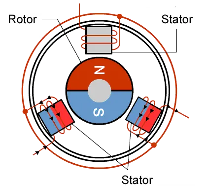
The Lorentz force law, which states that a current-carrying conductor experiences a force whenever it is placed in a magnetic field, is the same principle that governs the operation of a BLDC motor.
Working
A brushed DC motor and a BLDC motor operate on a similar theory. The current-carrying conductor suffers a force anytime it is placed in a magnetic field, according to the Lorentz force law. The magnet will experience an equal and opposite force as a result of the reaction force. The permanent magnet is moving while the current-carrying conductor is still in the BLDC motor.
The stator coils become electromagnets and begin to produce a consistent field in the air gap when they receive power from a source. Despite the fact that the source of supply is DC, switching causes an AC voltage waveform with a trapezoidal shape to be produced. Rotor rotation is maintained by the interaction between the permanent magnet stator and electromagnet stator.The matching windings were activated as the North and South poles when the windings were switched between High and Low signals. The motor rotates because the North and South poles of the permanent magnet rotor align with the poles of the stator.
Advantages
- Absence of brushes results in quiet operation (or low noise).
- Less electromagnetic noise
- Due to the lack of brushes, which would normally set a speed restriction, the machine operates at a high speed both when loaded and when empty.
- Long lifespan because the commutator system doesn't need regular maintenance or inspection.
- Low inertia and carrying windings in the stator result in a higher dynamic response.
- It has difficulties with its absence of a mechanical commutator.
- Permanent magnet rotor usage results in high efficiency.
Refferences
- https://skill-lync.com/projects/multi-quadrant-operation-of-dc-motor-in-simulink
- https://in.mathworks.com/help/physmod/sps/ug/speed-control-of-a-dc-motor-using-bjt-h-bridge.html;jsessionid=8db79836dfea77b64c33ca2e2395
- https://in.mathworks.com/help/physmod/sps/ug/dc7-four-quadrant-chopper-200-hp-dc-drive.html