Project
AIM
To study and analyze the BAJA All Terrain Vehicle (ATV) model using Simulink.
OBJECTIVES
Download the model of an all terrain vehicle from the given link and perform Simulation. To prepare a technical report of BAJA ATV model with and without Lookup Table.
THEORY:
Downloaded the file from the given link includes BAJA all terrain vehicle (ATV) with continuously variable transmission(CVT).
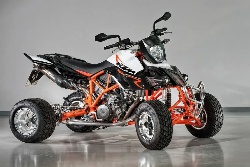
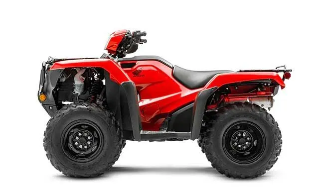
An all terrain vehicle is also known as Light Utility Vehicle(LUV), a quad bike, or simply a quad, as defined by the American National standard institute (ANSI); is a vehicle that travels on low-pressure tires, with a seat that is straddled by the operator, along with handlebars for steering control. The rider sits on and operates these vehicles like a motorcycle, but the extra wheels give more stability at slower speeds. Although most are equipped with three or four wheels, six-wheel models exists and existed historically for specialized applications.
Continuous Variable Transmission (CVT)
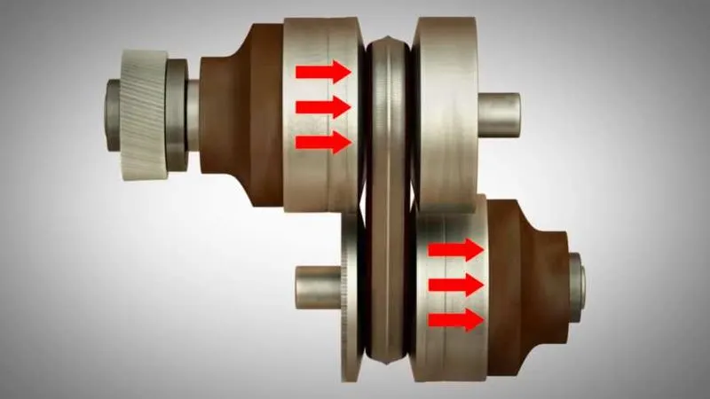
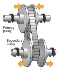
A CVT is an automated transmission that can change over a continuous range of gear ratios. It might enable the engine to run continuously at a set rpm even when the vehicle travels at different speeds. A little off-road vehicle is the BAJA. An off-road vehicle's suspension and chassis are crucial to its structural performance. the analysis of the static and dynamic behaviour of an all-terrain vehicle construction through simulation. The transmission ratio can be automatically changed by a pulley system, which allows for infinite variation between the highest and lowest gears without any noticeable steps or shifts. More usable power, improved fuel efficiency, and a smoother driving experience are all provided by them.
Here we can study about Some models of BAJA ATV
- BAJA ATV model Without lookup table
1. with dashboard
2. witout dashboard
- BAJA ATV model with mapped lookup table
1. with dashboard
2. witout dashboard
Model Explanation
The following blocks are used in the models
- Signal Builder-To input the brake,Throttle and CVT ratio.
- Simulink to PS converter
- Solver configuration
- Mechanical Refference
- Generic Engine- To run the with speed and torque values as input.
- PS to Simulink converter
- Scope
- Display
- Inertia- To represent the solid inertia.
- Rotational motion sensor- Sense the rotational motion from the engine and give output as rpm.
- Variable gear ratio- To vary the speed according to the gear ratios.
- PS Terminator
- Double shoe brake- To apply brake to the vehicle when needed.
- Tire- For transportation
- Vehicle body-To represent the BAJA ATV model body.
- Knob-To adjust the brake and throttle inputs.
- PS constant- For constant physical signal.
- Rotational free end
- Custom measure guage
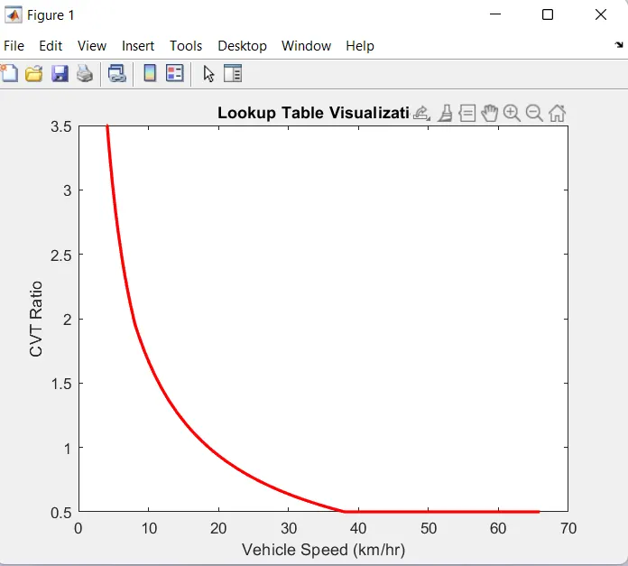
- Lookup Table- To insert the cvt values from the workspace.
- Simple gear- adjust the speed of the engine with pre-defined gear ratio.
- Step- To adjust the input value for a defined intervals.
1. BAJA ATV model without Dashboard
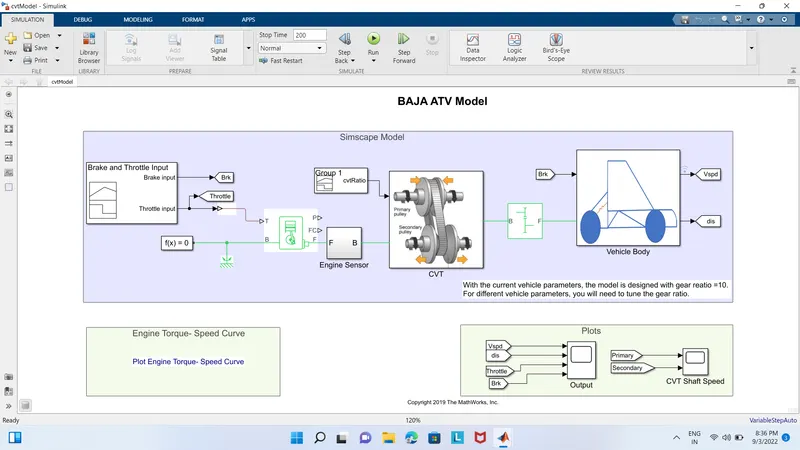
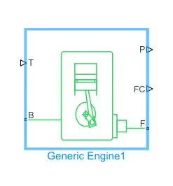
The signal builder block which is used to give brake and throttle input. The signals are given to the generic engine block. The throttle input signal T lies between zero and one which specifies the torque demanded from the engine as a fraction of the maximum possible torque. F&B are mechanical rotational conserving ports associated with the engine crankshaft and engine block. Connections P& FC are physical signal output ports through which engine power and fuel consumption rates are reported. The engine sensor block measures angular velocity or angle in a mechanical rotational network.
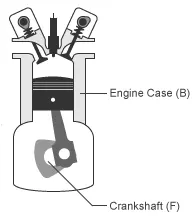
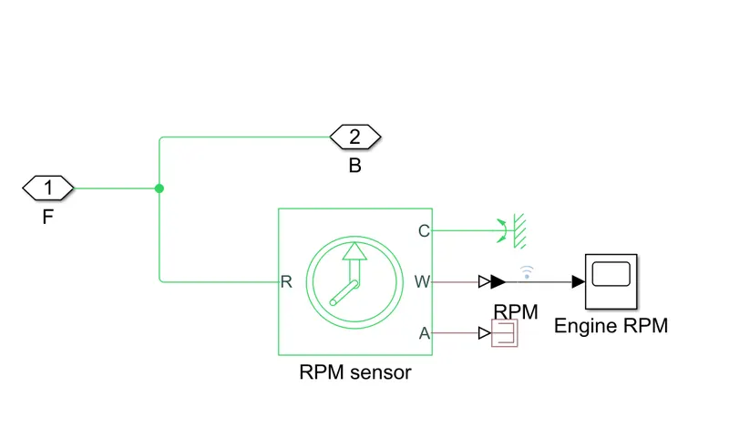
Ideal mechanical rotational motion sensor (RPM Sensor), R port is relative to port C. W is angular velocity and A is angular displacement. The measurement is positive when the motion at R is greater than the motion at C. The system is connected to a simple gear block followed by a subsystem of CVT and Vehicle body. Simple gear represents a fixed ratio gear or gearbox. No inertia or compliance is modelled in this block.
Continous Variable Transmission (CVT)
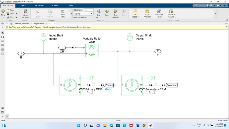
Inertia;
Block represents an ideal mechanical rotational inertia and has one mechanical rotational conserving port. The block positive direction is from its port to the reference point. This means that the inertia torque is positive if the inertia is accelerated in a positive direction.
In this model two inertia blocks represents the primary pulley and the output shaft inertia represents the secondary pulley inertia. Then the variable gear ratio gear box such as implemented by mechanical belt CVT,electric or hydraulic transmissions. The physical input ‘r’ defines the ratio of input to output angular shaft velocity. Connection B (base) & F (follower) are mechanical rotational conserving ports. Specify the relation between B&F rotation directions with the output shaft rotates parameter.
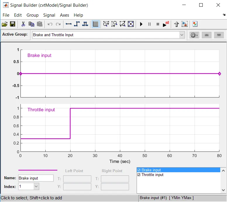
Brake and Throttle input from signal builder
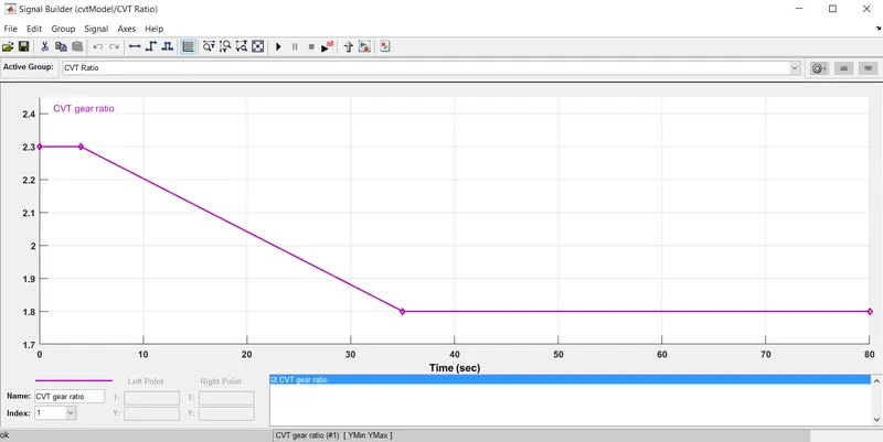
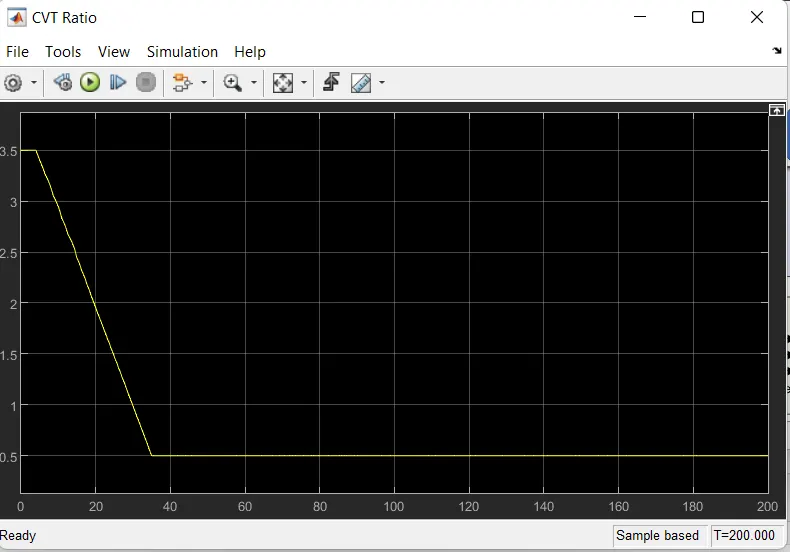
CVT ratio graph
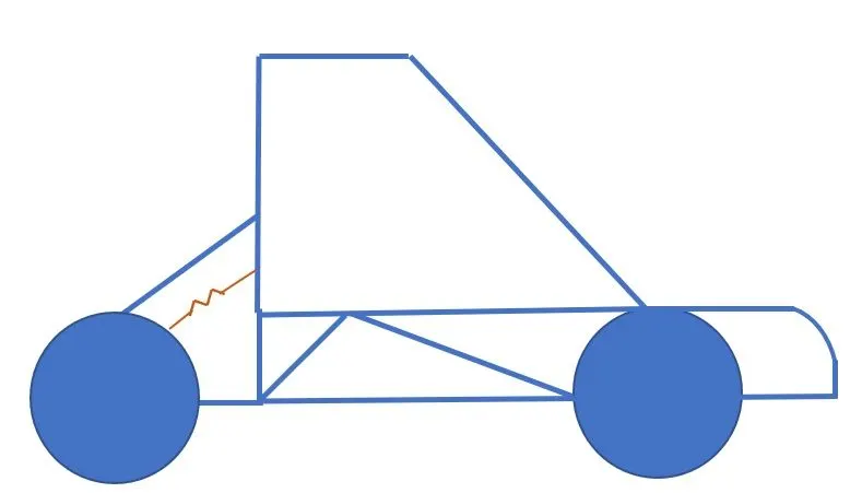
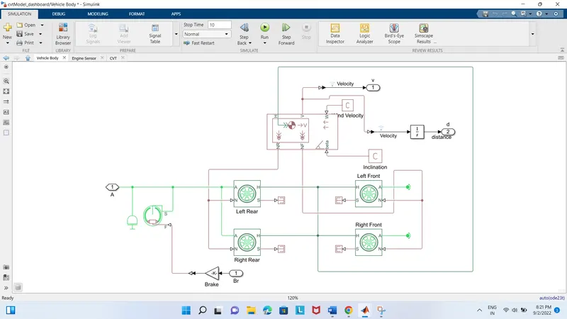
The model contains mainly four tire blocks, brake shoe and vehicle body.
Tire;
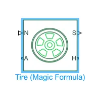
The wheels work on the magic formula.
N- Normal forces
S- Slip
A- Axle
H-Hub
The tire block models a with tire longitudinal behavior given by the magic formula, an empirical equation based on four fitting coefficients. The tire as a rigid wheel-tire combination in contact with the road and subject to slip. When torque is applied to the wheel axle the tire pushes on the ground and transfers the resulting reaction as a force back on the wheel. This will push the wheel forward or backward.
Double shoe brake;
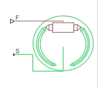
There are four wheels in which the rear wheels are connected to the output shaft from the CVT through the axle making it arear wheel drive. Which will helps apply brake power to the rear wheels. The vehicle body connected to the wheels and the hub of the wheels according to the connections to simulate the working of the body.
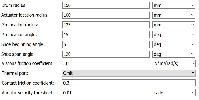
Brake shoe parameters
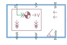
Beta present in the vehicle body represents the angle of inclination of the road at which the vehicle is travelling. The port W which is used to provide head wind speed.
NR- Rear axle normal force
NF- Front axle normal force
H- Horizontal motion
V- Longitudinal velocity
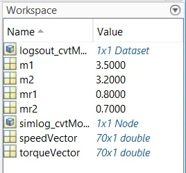
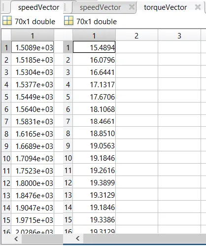
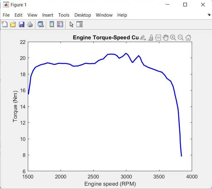
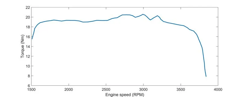
Engine torque speed curve
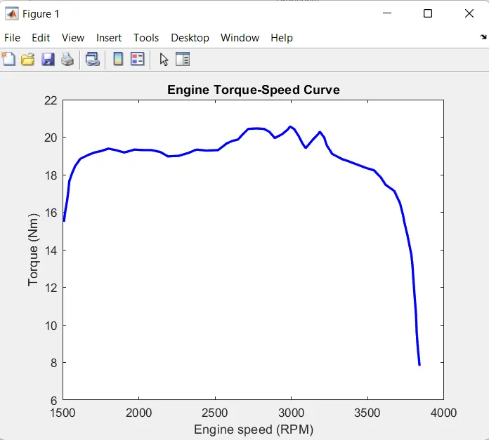
Engine speed plot
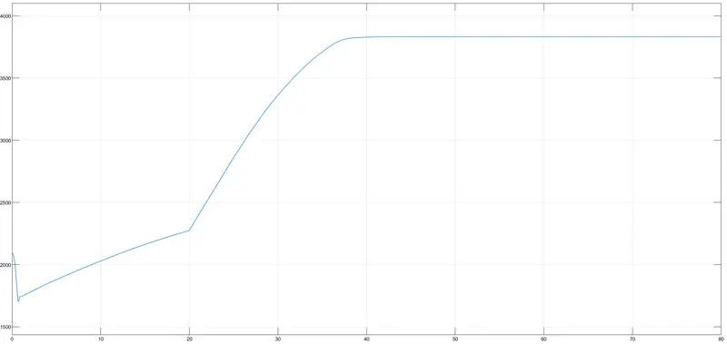
Speed vs Throttle
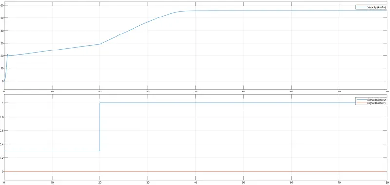
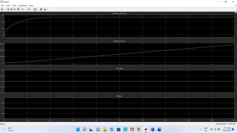
Output
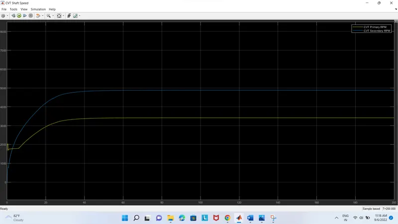
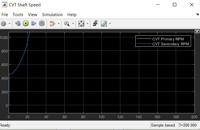
CVT shaft speed
2. BAJA ATV with dashboard
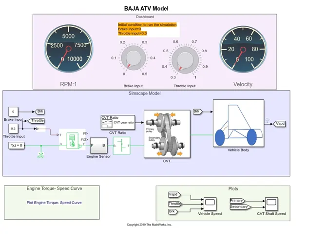
A Simulink model for the BAJA ATV model including the dashboard is given below. The rest of the parts and subsystems are common in the above part. The dashboard of a vehicle is a control panel which displaying instrumentations and controls. Usually it is situated in front of the driver.
In this model the initial conditions are follows,
Brake input=0 & Throttle input =0.3.
Here the signal builder block is replaced with two separate constant blocks for the throttle and brake which connected to the dashboard.
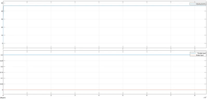
Dashboard vehicle speed
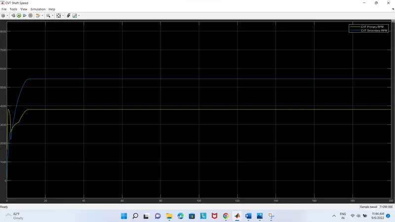
CVT shaft speed
3. Lookup Table Models
Lookup table
It is a set of data that approximates a mathematical function by mapping input values to output values. Simulink uses a lookup operation to find the corresponding output values in the table given a set of input values. The block estimates the output values based on nearby table values if the lookup table does not specify the input values
BAJA ATV mapped lookup table model without dashboard
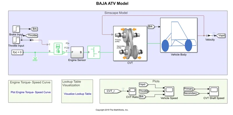
The model which the process is same as the process of BAJA ATV model without dashboard. But the throttle and brake inputs are controlled by the user with the knob followed by the vehicle speed. In this model we use a PS lookup table block. The brake and throttle inputs are given as step block values and CVT ratio is given through the lookup table block.
In brake input the step time is 35 and in throttle input the step time is 20. In previous cases , the gear ratios were given to CVT subsystems as signal by signal builder blocks. Here the gear ratios are given externally using lookup table.
Engine torque speed curve
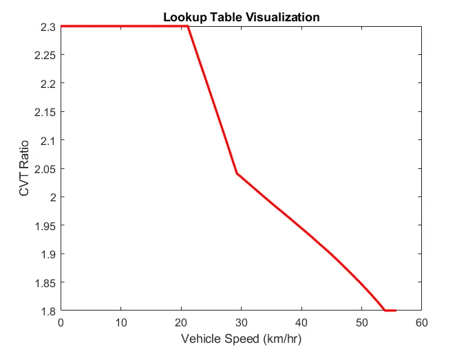
Lookup Table Visualization
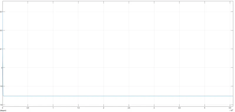
CVT ratio
Vehicle speed

Vehicle Shaft speed
BAJA ATV mapped lookup table model with dashboard.
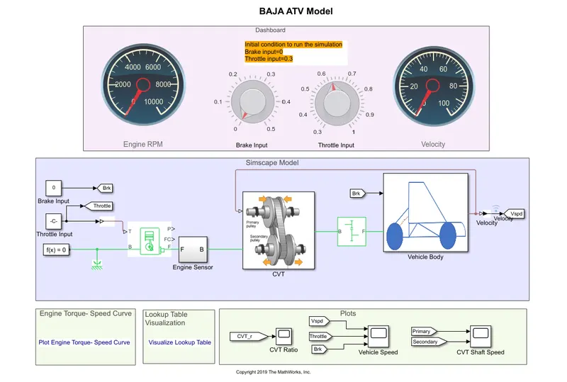
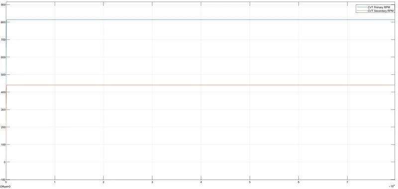
The engine in this model is pre-set to run at 3300 rpm with a 0.3 throttle value and a speed of 45 KMPH. The CVT ratio was predetermined to be 2.3 for the engine's minimum speed and 1.8 for its highest speed. The initial throttle value of 0.3 is attained when the simulation is launched. When the throttle is raised, the CVT ratio moves toward 1.8, where the state is maximum engine speed, so that it is close to 1.85. The CVT ratio will increase toward 1.85 as the throttle is closed. As brakes is applied, the CVT ratio rises to enable it to reach its minimum speed of 2.3, which is the closest state.
After running the simulation we got the results they are given below.
Lookup table Visualization
Speed vs torque curve
CVT ratio
CVT Shaft speed
These are processed by the feedback arrangement of the model. This is like as adaptive cruise control method.
Adaptive cruise control (ACC) is a cruise control advanced driver aid system that is available for road vehicles. It automatically modifies the speed of the vehicle to maintain a safe distance from vehicles in front of it. As of 2019, it also goes by 20 different names that all refer to the same fundamental capability. The term "dynamic cruise control" also applies to this. On-board sensors' sensor data is used for control. Such systems may make use of a radar, laser, or camera arrangement to enable the vehicle to brake when it notices another vehicle is approaching up ahead and accelerate when traffic permits. Future generations of intelligent cars are expected to have significant amounts of ACC technology. By maintaining the road's capacity and improving passenger convenience and safety, technology
Conclusion Four models of the BAJA ATV vehicle have been simulated, and the results are presented for each model.
Refferences
- https://www.mathworks.com/matlabcentral/fileexchange/70576-baja-all-terrain-vehicle-atv-model
- https://coeng.uaa.alaska.edu/innovation/?p=259
- https://en.wikipedia.org/wiki/All-terrain_vehicle
- https://en.wikipedia.org/wiki/Adaptive_cruise_control