Week -2
1. Make a Simulink model of Doorbell using solenoid blocks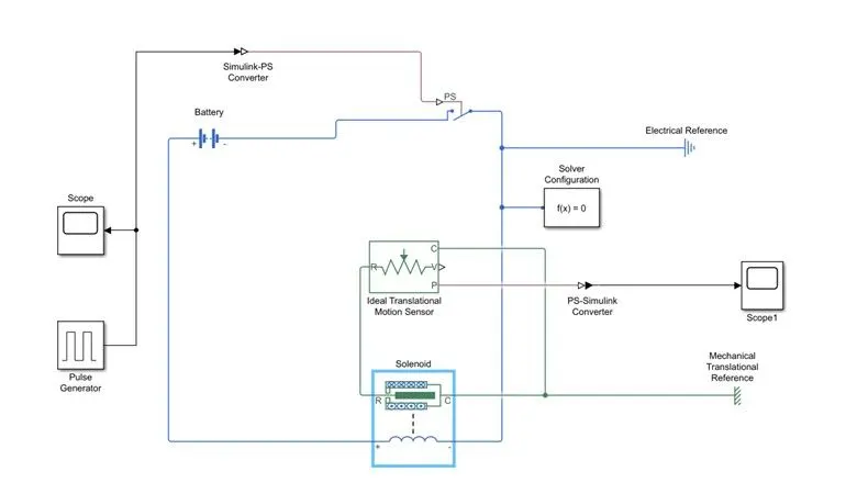
The model is created by using the following blocks
- Pulse generator
- Scope
- Switch
- battery
- PS-Simulink &Simulink-PS converter
- Ideal translational motion sensor
- Solver configuration
- Electrical reference
- Mechanical Translational reference
- Display
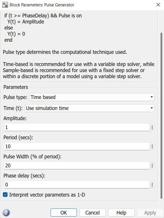
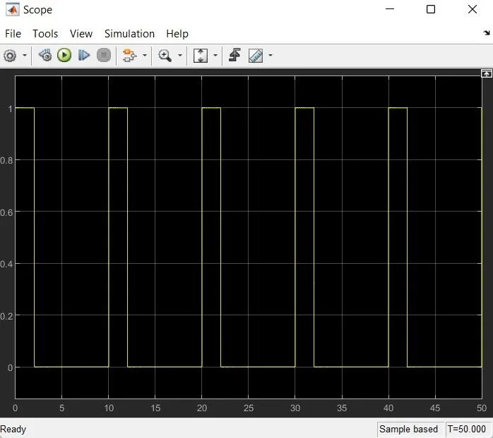
The pulse generator which is used to generate the signal to input to the Switch. The Simulink -PS converter which convert the signal into physical signal. When the switch is on for Two seconds, the current passing through the Solenoid and it makes the plunger to create a displacement according to the solenoid property. This can be caught by Ideal translational motion Sensor and finally we get the output. The switch is closed for 2 seconds and after that the switch is open. A solver configuration is connected to an electrical circuit to solve all parameters before the beginning of a simulation. The following figure describes the pulse generator functioning.
Input
This is the Input pulse.
Output
We can use the Solenoid In two ways
- Ports R to moves towards port C
- Port R moves away from port C
The below mentioned plots are the Solenoid arrangement in two ways.
Ports R to moves towards port C
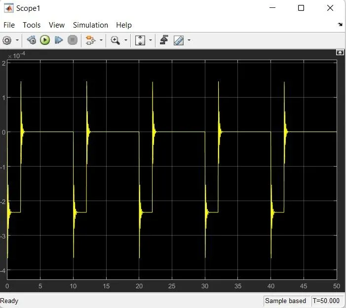
Port R moves away from port C
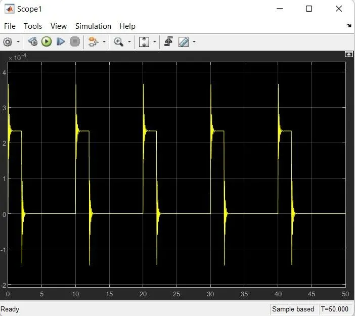
2. Thermistor to sense the temperature of a heater & turn ON or turn OFF the Fans as per the conditions
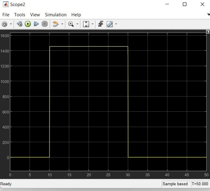
- From 0 to 10 secs - 20 degree Celsius(293 k)
- 10 to 30 secs - 27 degree Celsius (300 k)
- 30 to 50 secs - 23 degree Celsius (296 k)
Simulink Model
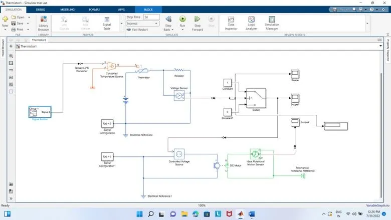
This model is created by using the following blocks
- Signal builder
- Simulink-PS & PS-Simulink converter
- Controlled Temperature Source
- Thermistor
- Resistor
- Voltage source
- Solver configuration
- Electrical Reference
- Controlled voltage Source
- DC motor
- Ideal Rotational Motion Sensor
- Switch
- Constant
- Scope
- Mechanical reference
- Display
Thermistor is a device which measures temperature. Its working is based on the relationship between resistance and temperature. Here we put the input according to the given condition, For that we use signal builder block
- From 0 to 10 secs - 20 degree Celsius(293 k)
- 10 to 30 secs - 27 degree Celsius (300 k)
- 30 to 50 secs - 23 degree Celsius (296 k)
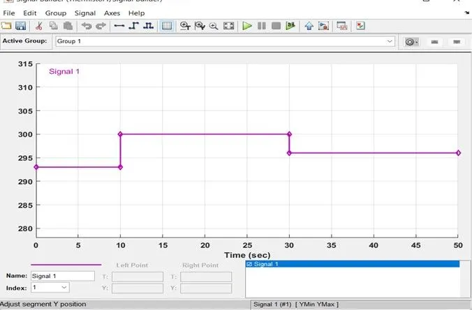
The temperature source is provided with input signals as per the given conditions. The output from the voltage sensor is given to the switch. A DC motor used instead of a fan which has one end is connected to switch output and other end to a rotational motion sensor.
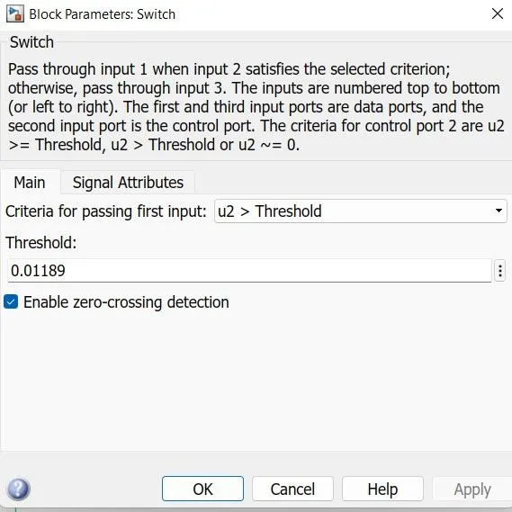
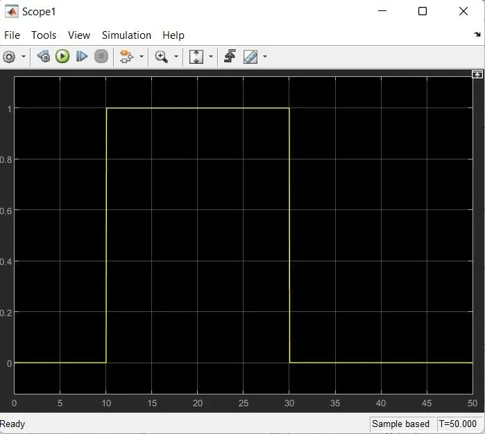
Here the switch block which passes through the first input signal based on the value of the second input. The first and third inputs are data inputs. The second input is control input .By the use of a PS-simulink converter convert output voltage signal from voltage sensor to Simulink output signal and fed into Switch. We change the threshold value of switch to 0.01189 so that switch only works for the given condition. Two constants 1 & 0 are connected to switch port 1 & 3 respectively.
OUTPUT
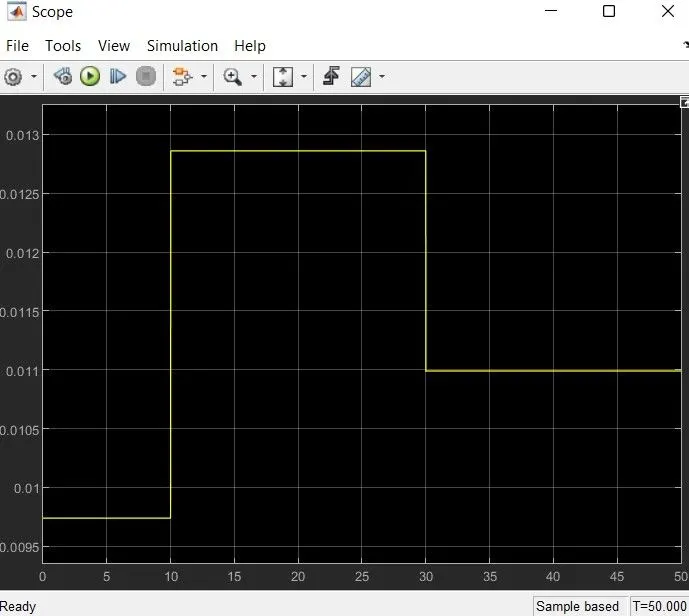
Voltage v/s Time
Switch ON/OFF plot
Angular velocity v/s time of DC motor