Week-7 Challenge: DC Motor Control
1 (a). Speed control of a DC motor using BJT H-bridge:
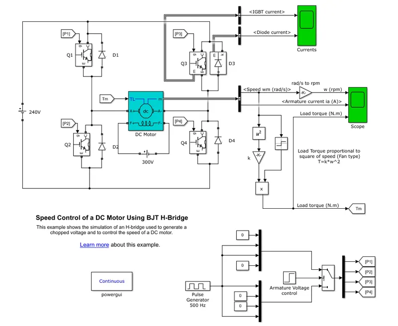
- In the above model, the DC Motor is controlled using four quadrant chopper.
- When utilised in power switching applications, BJT functions as an IGBT. Between the collector and the emitter, a forward voltage develops when it is conducting.
- Hence, the BJT device may be modelled using the IGBT block.
- There are four BJT/Diode pairings in the H-bridge (BJT simulated by IGBT models).
- The simultaneous switching of Q1 and Q4 or Q2 and Q3 involves two transistors.
- When Q1 and Q4 are lit, a positive voltage is given to the motor, and when Q1 and Q4 are turned off, diodes D2-D3 function as free-wheeling diodes.
- When Q2 and Q3 are lit, a negative voltage is provided to the motor, and when Q2 and Q3 are turned off, the diodes D1–D4 function as free-wheeling diodes.
(b).
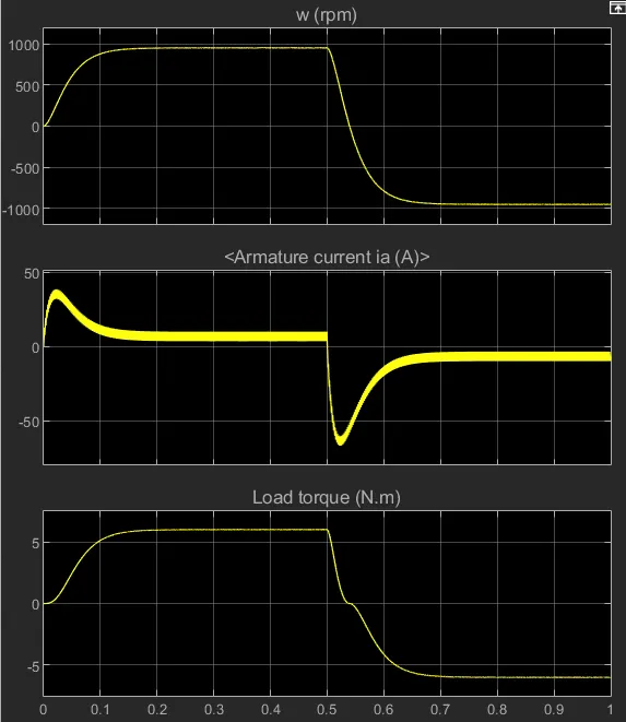
- The armature current shoots instantaneously as seen the figure above.
- This results from the motor's instantaneous transient switching between the positive and negative voltage value.
(c).
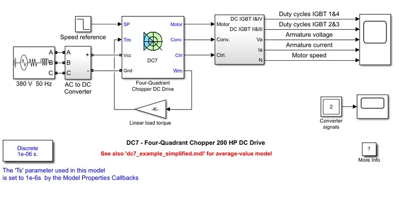
Comparison between H-Bridge and Four-quadrant chopper:
| H-Bridge | Four-quadrant chopper |
| 1. Operates only in forward motoring and reverse motoring region. | 1. Operates in all four regions, i.e., forward motoring, forward regenerative braking, reverse motoring and reverse regenerative braking |
| 2. Works on DC voltage | 2. Works on rectified AC coltage. |
| 3. Low efficiency. | 3. High efficiency. |
2. 2-Quadrant chopper:
Simulink model-
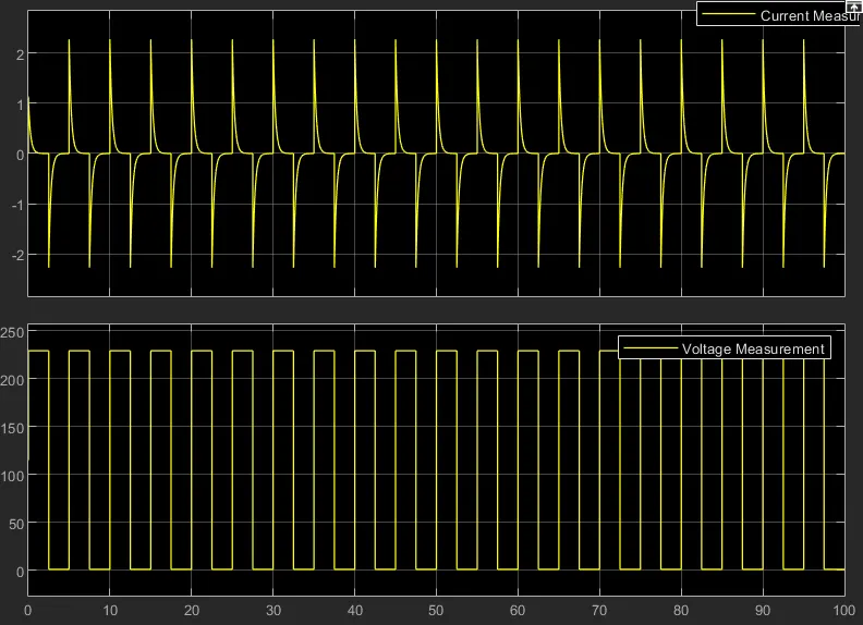
Plot-
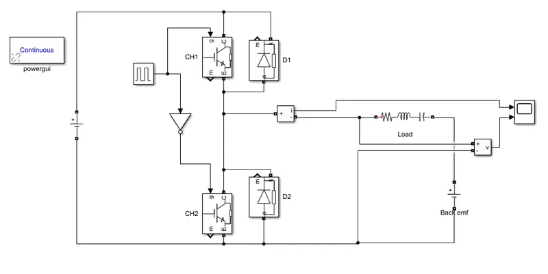
- IGBT switch CH1 and diode D1 constitute one chopper and the IGBT switch S2 and
diode D2 form another chopper. - The switches CH1 and CH2 are closed alternately. To avoid a direct short-circuit across the
source, care is taken to ensure that CH1 and CH2 do not conduct at the same time. - DC voltage source of 230 V is supplied to the circuit and series RLC branch is provided as load with back emf.
- The voltage and current is measured using voltage and current measurements.
- When CH1 is ON, CH2 remains OFF. Voltage is the source voltage and current is positive.
- When CH2 is ON, CH1 reamins OFF. Voltage becomes zero and the current goes negative.
- The sharp shoot is current is due to sudden switching of the switches.
3. Operation of BLDC motor
- What is a BLDC motor?
A brushless DC motor, also referred to as synchronous DC motor, is a permanent magnet synchronous electric motor that is powered by direct current electricity and achieves electronic controlled commutation instead of mechanical commutation. The major difference between a conventional brushed motor and a brushless motor is the replacement of mechanical commutator with an electric switch circuit. A BLDC Motor senses the magnetic field generated by the stator and the rotor revolve at the same frequency. Of the family of permanent magnetic motors, the brushless DC (BLDC) motor drive is the most promising candidate for EV and HEV application.
- Advantages of BLDC motor include:
- High efficiency
- Compactness
- Ease of control
- Low maintenance, great longevity, and reliability
- Low noise emissions
- Construction of BLDC Motor:
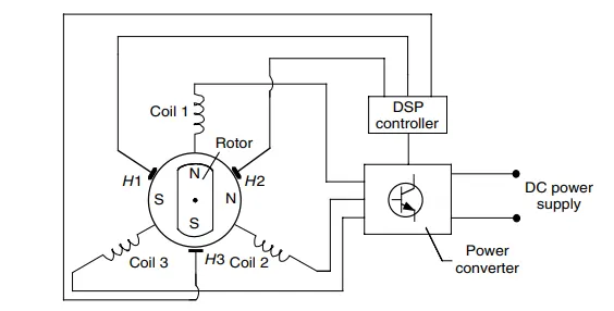
- The figure aboe is a schematic representation of BLDC motor drive.
- A BDLC motor drive consists mainly of the brush-less DC machine, a DSP-based controller, and a power electronics-based power converter.
- BLDC motor works on the principle similar to that of a conventional DC motor, i.e., the Lorentz force law.
- Position sensors H1, H2, and H3 sense the position of the machine rotor.
- The rotor position information is fed to the DSP-based controller, which, in turn, supplies gating signals to the power converter by turning on and turning off the proper stator pole windings of the machine.
- In this way, the torque and speed of the machine is controlled.