Project - Speed Control of a Direct Current (DC) motor
Aim: Speed control of DC motor
Solution:
DC Motor Design parameters-
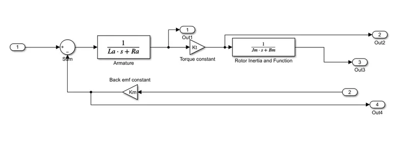
Jm=0.01; %moment of inertia of motor in kg-m^2
Bm=0.1; %motor viscous friction constant in N-ms
Km=0.01; %back emf constant in V/rad/s
Kt=0.01; %motor torque constant in NmA
Ra=1.0; %armature resistance in ohm
La=0.5; %armature inductance in henry
To find Kp and Kd gains for PID controller-
A = [-Bm/Jm Kt/Jm; -Km/La -Ra/La]; % Matrix A
B = [0; 1/La]; % Matrix B
fn = 1; % Natural frequency in Hz
wn = 2*pi*f; %Angular frequency in rad/s
zeta = 0.6; % under-damped system
p1 = -zeta*wn+wn*sqrt(zeta^2-1);
p2 = -zeta*wn-wn*sqrt(zeta^2-1);
P = [p1;p2];
K = place(A,B,P);
Kp = K(1); % Proportional gain
Kd = K(2); % Differential gain
Model specifications-
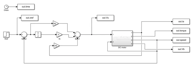
i. Step function block is used to give reference speed-
Step time:0
Initial value:0
Final value: 50
ii. Proportional and Differential gain-
Kp= 32.0301
Kd= -2.2301
Model settings-
Type: Fixed type
Solver type: Ode4(Range-Kutta)
Fixed step size: 0.01
Simulation time=10 seconds
Simulink Model-
DC motor design-
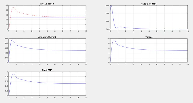
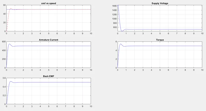
Plots-
- For Ki= 10, Kp= 32.0301, Kd= -2.2301
- For Ki= 35, Kp= 32.0301, Kd= -2.2301
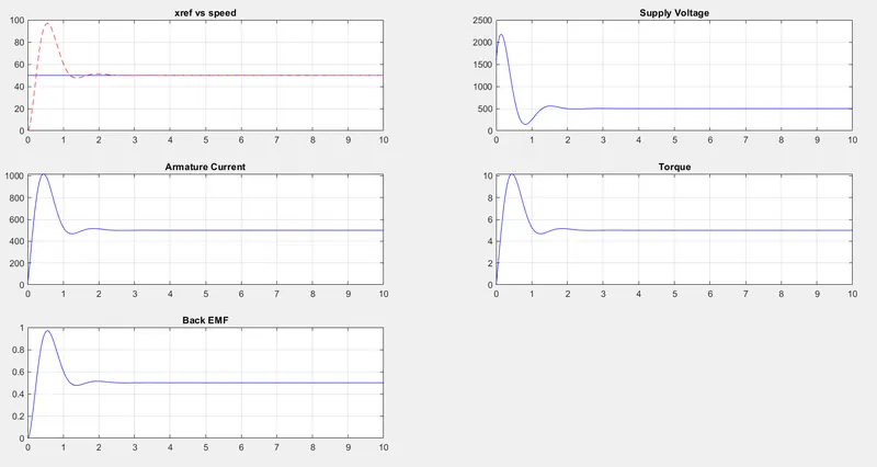
- To maintain overshoot, settling time and steady state error in desired level, PID gains are slightly altered for the below graph to make the system more reliable and stable i.e., Ki= 60, Kp= 32.0301, Kd= 0.1
Sumarry:
- PID controller controls the DC motor speed at the desired value with least error.