Week-7 Challenge: DC Motor Control
___Q1___
A. Explain a MATLAB demo model named ‘Speed control of a DC motor using BJT H-bridge.
B. Comment on the armature current shoot-up from the scope results.
Answer :
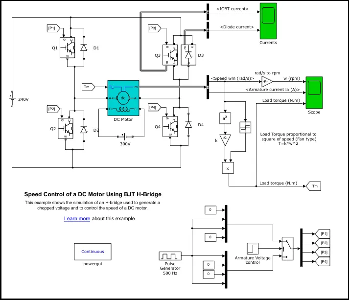
CONSTRUCTION :
- The model is constructed using a BJT H-bridge, a Pulse Width Generator, a Fan type load and a DC motor.
- BJT H-bridge : Constructed using 4 IGBTs, namely Q1, Q2, Q3 & Q4 with respective freewheeling diodes.
When a forward voltage `V_f`is developed between collector and emitter, the IGBT starts conducting and hence can be modelled as a BJT.
It is not simulated using a gate current here rather, it is controlled by a Simulink signal (1/0).
- Load : A fan type load is modelled here where Torque is a function of speed squared. `T = k*w^2`
- DC Motor : A preset block of DC motor is used.
Parameters - 5 HP, 240V, 1750 RPM, Field voltage 300V.
Mechanical input is Torque.
WORKING :
- The BJTs are controlled from a PWM, where the duty cycle is varied from 0-100%
- The armature voltage is varied from 0-240V using the PWM..
- Two BJTs are switched simultaneously Q1 & Q4, a positive voltage is applied across the motor.
- Similarly when Q2 & Q3 are switched at t = 0.5 seconds, a negative voltage is applied across the motor and the motor rotates in opposite direction.
OBSERVATION :
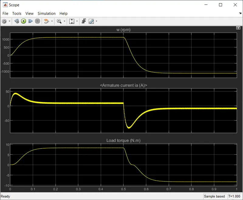
1- Duty cycle = 80%, amplitude = 1.
RPM = 1118, Torque = 8.3 Nm,
Ia = 44 A(at start) Ia = 85 A(at switching)
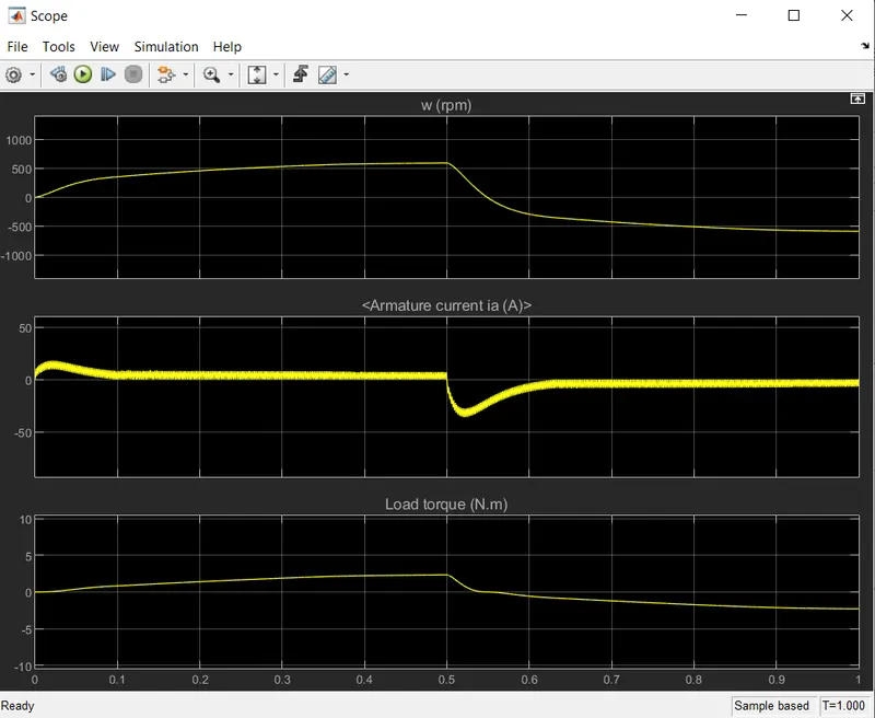
2- Duty cycle = 60%, amplitude = 1.
RPM = 592, Torque = 2.3 Nm,
Ia = 16 A(at start) Ia = 42 A(at switching)
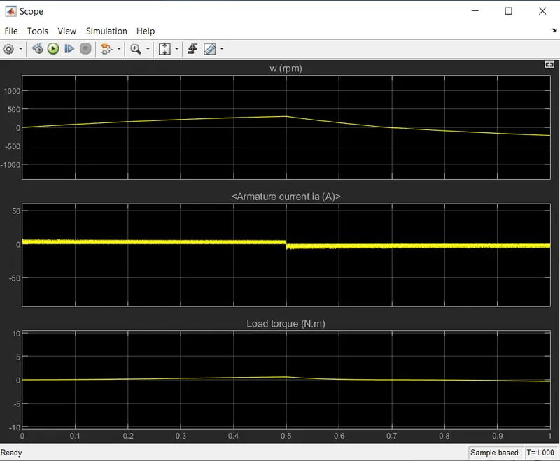
3- Duty cycle = 40%, amplitude = 1.
RPM = 300, Torque = 0.5 Nm,
Ia = 6 A(at start) Ia = 8 A(at switching)
CONCLUSION :
When the BJTs are fired we see increase in armature current then it becomes steady. But when the motor direction changes armature current shoots up due to switching and heat losses. But as the duty cycle is reduced we see reduction in the shoot up of armature current and settling time.
C. Compare BJT H-bridge model with Four-Quadrant chopper DC Drive model.
| BJT H-Bridge | 4-Quadrant Chopper |
| Only works in 2 quadrant i.e. Forward Moroting & Reverse Motoring. | Works in all 4 quadrant i.e. Forward Moroting, Forward Braking, Reverse Motoring, Reverse Braking. |
| Regeneration is not possible. | Regeneration is possible due to working in forward and reverse braking. |
| Speed reference is not needed. | Speed refernce is needed hence speed control possible. |
| DC source is used directly. | Inverter is required to convert AC to DC. |
___Q2___
AIM : Develope a 2-quadrant chopper using simulink & explain it working.
CONSTRUCTION :
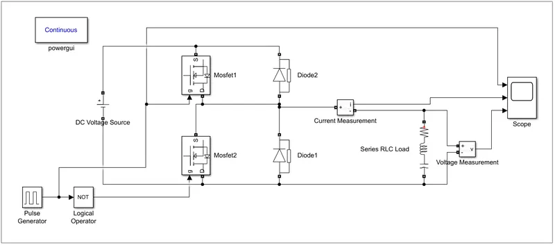
- 2 MOSFET switches.
- 2 Diodes.
- DC voltage source.
- RLC load.
- Pulse Generator.
- NOT logical operator.
- Current & Voltage measurement.
WORKING :
- A pulse of amplitude 5 with 50% duty cycle is used to switch on the MOSFET switches and a not gate to operate one MOSFET at a time.
- When MOSFET 1 is turned on, source voltage gets applied across the load and the current flows from souce to the load.
- The inductor stores the energy and when the MOSFET 1 is switched off, the freewheeling diode D1 starts conducting. The output voltage equals the source voltage.
- The direction of load current reverses when D1 starts conducting. The current flows from load to the source.
- Similarly when MOSFET 2 is turned on, source voltage gets applied across the load and the (negative)current flows from souce to the load.
- The inductor stores the energy and when the MOSFET 2 is switched off, the freewheeling diode D2 starts conducting. The output voltage equals the source voltage.
- The direction of load current (negative) reverses when D2 conducts.
- We always get positive output voltage across load due to freewheeling diode.
OBSERVATION :
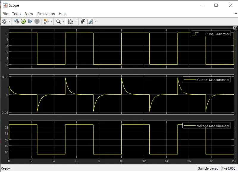
We can see the output voltage is always positive.
The current is positive for MOSFET 1 and negative when MOSFET 2 is switched on.
CONCLUSION :
After successful simulation of 2-Quadrant chopper, we can see the current flows in both direction i.e. positive and negative direction. With output voltage always remaining positive.
___Q3___
Explain in a brief about operation of BLDC motor.
BLDC motor as the name suggest are brushless motor, that doesnt use brushes for commutation but rather they are electronically commutated.
CONSTRUCTION :
It consist of a Stator & Rotor.
Stator - Made of stacked steel laminations with slots for windings.
Rotor - Made of permanent magnets, usually placed on the outer periphery of the shaft.
The number of pole pairs vary according to application and are placed alternatively.
Position Sensors - Hall sensors are used to detect the exact position of the rotor.
WORKING :
- Its operation is based on the attraction and repulsion between magnet poles.
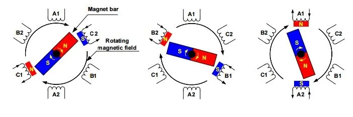
- A three phase construction is shown above, the rotor is assumed as a single permanent magnet.
- When current flows through C1 & C2 it generates a magnetic pole, it attracts the closest pole of the permanent magnet of rotor.
- The rotor moves as the current shifts to adjacent winding B1 & B2 then A1 & A2. Sequentially charging each winding will generate a rotating magnetic field which attracts and repels the poles on rotor.
- To increase the efficiency, two coils can be energised simultaneously to produce 2 poles pair of different polarity, one to attract the rotor and other to repeal the rotor at the same time.
- For `360^o`rotation, 6 possible combinations of coils A, B & C are shown in diagram below.
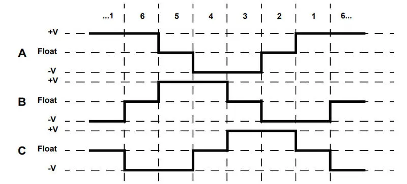
- From this we can confirm that at any time, one phase is positive, one phase is negative and third phase is idle/floating.