Week-6 Challenge: EV Drivetrain
___Q1___
Which types of power converter circuits are employed in electric and hybrid electric vehicle?
Answer :
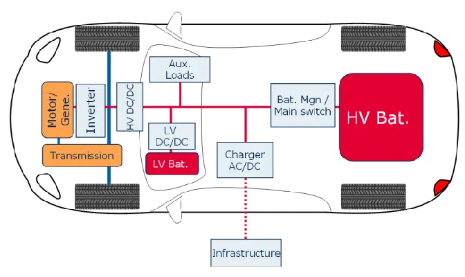
There are mainly 3 types of power converter used in an EV or HEV. Diagram above shows their location.
1- AC to DC converter.
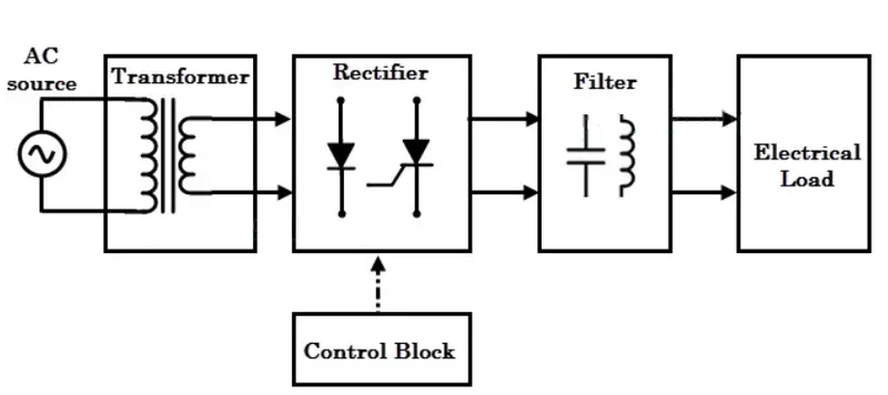
- It is also called as Rectifier.
- It converts AC supply into DC supply.
- The block diagram is shown above, which consist of transformer, rectifier circuit, filter and control unit.
- The transformer reduces the supply voltage to circuit operating range, the rectifier converts AC wave to DC wave which is pulsed DC, which in turned is smoothened with a filter circuit to get pure sinusoidal wave.
- In an EV, AC/DC converter is used in a charger circuit, which is used to charge the battery pack. It can be a onboard charger or an offboard charger.
2 - DC to DC converter.
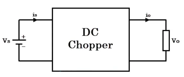
- It is also called as Chopper.
- It converts fixed input DC voltage to variable/fixed output DC voltage.
- It consist of power electronics switching devices such as thyristors which are controlled with Pulse Width Modulation technique.
- They are of 2 types : Buck - step-down chopper & Boost - step-up chopper.
- In an EV, DC/DC converter is used in DC drives, input for DC traction system, low voltage DC equipments like wiper, window pane devices, automatic door opening/closing
3 - DC to AC converter.
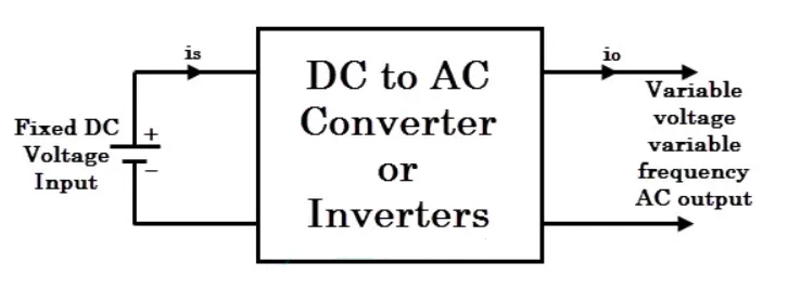
- It is also called as Inverter.
- It converts DC supply to AC supply of variable or fixed frequency.
- In an EV, DC/AC converter is used to power AC traction system, power steering etc.
___Q2___
AIM : To find the steady state speed of EV when duty cycle is 70%.
GIVEN : Motor & Controller Parameters -
- Rated Armature voltage = 72V
- Rated Armature current = 400A
- Armature Resistance = 0.5 `Omega`
- Motor constant `k_phi` = 0.7 volt second
- Vehicle Speed-Torque equation = `T_v = 24.7 + (0.0051)omega^2`
THEORY :
Given Speed-Torque equation = `T_v = 24.7 + (0.0051)omega^2` ...............(1)
now the duty cycle is 70% of original.
therefore, armated voltage becomes 0.7 * 72 = 50.4 V
Speed - Torque equation is given by -
`T_v = (V*k_phi)/ R_a - (omega * k_phi^2)/R_a`
putting above values
`T_v = 70.56 - 0.98 omega`................(2)
From (1) & (2)
`24.7 + (0.0051)omega^2 = 70.56 - 0.98 omega` ..............(3)
rearranging equation (3)
`0.0051 omega^2 + 0.98omega - 45.86 = 0`....................(4)
solving equation (4) using matlab for `omega`
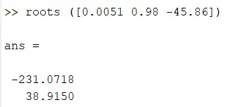
we get roots as 38.915 & -231.0718.
Neglecting negative value, we get `omega = 38.915 (rad)/sec`
CONCLUSION : The steady state speed when duty cycle was changed to 70% is 39.915 rad/sec.
___Q3___
Develop a mathematical model of a DC Motor for the below equation using Simulink.
Given Equation - `omega = V/k_phi - (Ra)/k_phi^2*T`
Simulink Model -
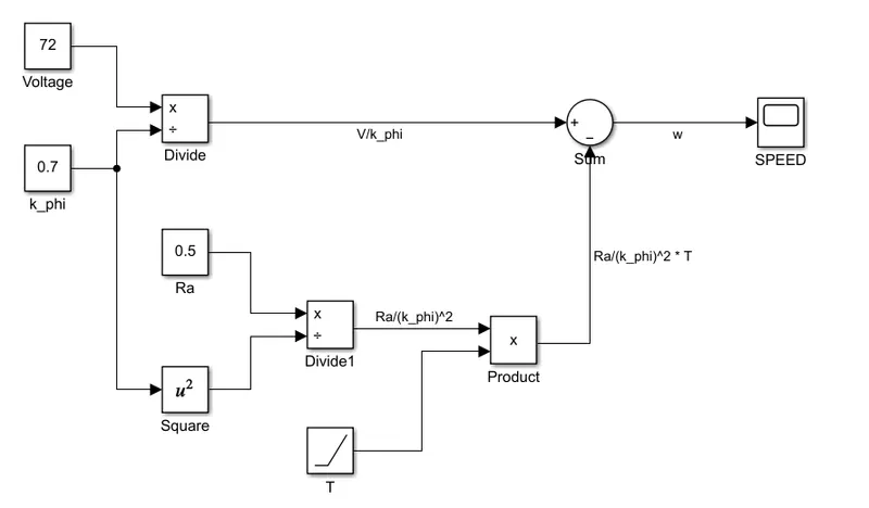
OUTPUT : Voltage (V) = 72 V
Armature Resistance (Ra) = 0.5 `Omega`
`k_phi` = 0.7 volt second.
Torque (T) = ramp (increasing load)
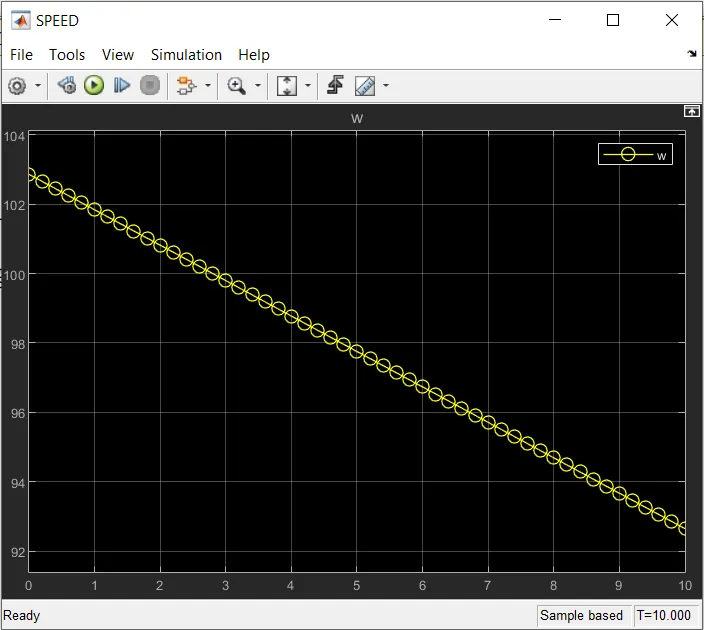
CONCLUSION : From the plot we can see inverse relation between speed and torque. As torque increases speed decreases of DC motor.
___Q4___
The author talks about ICE and its types. He says only the best of various types would have been in production, but such was not the case. As different type suit different requirements and same is the case for Electric Vehicle. Lead acid batteries, DC brush motors, contactor controllers have been replaced by lithium batteries, brushless motors and inverters. The same fight which different types of ICE had will go on in EV industry especially brushless vs induction machine.
While comparing both motors, an inverter is necessary for brushless DC motor to work efficiently as the rotor needs the stator current to be varied continuously. For an induction motor, stator construction is virtually identical with a brushless DC motor. Rotor in induction motor is a shorted structure, which produces torque when induced current interacts with supply voltage. One reason for success of induction motor is that they are directly compatible with the supply voltage and does not require an inverter alike DC motor. But they are also not without limitations likes they cannot operate on DC, constant speed operation, limited starting torque and limited running peak torque when compared with DC motor. Yet all this limitations can be worked around with an inverter they can work on DC, by adjusting inverter frequency speed variation can be achieved, with a feedback loop exact frequency can be produced to enhance torque performance and the motor is ready for vehicle operation.
Brushless DC also has some advantages like less rotor heat, easy rotor cooling, higher peak point efficiency due to operation on unity power factor (for induction it is 0.85). But with permanent magnets, magnetic field cannot be adjusted hence the `I^2R`losses, eddy currents & hysteresis cannot be managed which affects the efficiency. In contrast induction motor's magnetic field can be adjusted and hence average efficiency may actually be better.
From cost point of view, permanent magnet rotor and forces acting on it and low cost of inverter for induction motor, they are likely to be cheaper. But from control point of view they are more difficult which increases the developmental cost, but not recurring cost.
The author concludes that brushless DC motors will continue to dominate in hybrid market whereas induction will dominate in pure EV. Whatever may be the case both drives will work in tandem during the coming golden era of hybrid and EV.