Project - Speed Control of a Direct Current (DC) motor
AIM : Designing a Simulink model for DC Motor and using a PID controller to maintain desired speed of DC Motor.
THEORY : DC Motor circuit is as follows.
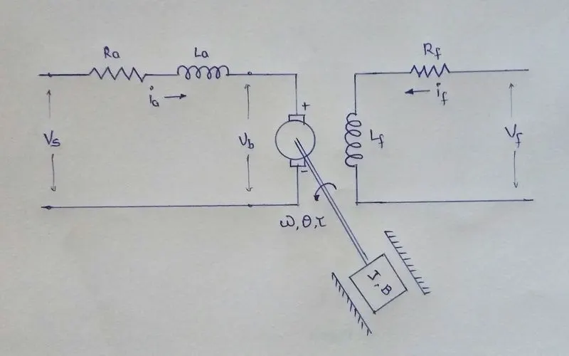
Applying KVL to DC motor circuit.
Vs = Ra*ia + La*(dia/dt) + Vb
Vb = Km*(dtheta/dt)
Therefore, Vs = Ra*ia + La*(dia/dt) + Km*(dtheta/dt) ...........(1)
Angular Velocity, w = theat_dot .........(2)
Differential Equations : -
i = (-Km/La)theta_dot - (Ra/La)i + (1/La)Vs ..........(3)
theta_dot_dot = (-B/J)theta_dot + (Kt/J)i ..........(4)
Converting to state-space
d/dt | theta_dot | = | -B/J Kt/J | |theta_dot| + | 0 | Vs
| i | | -Km/La -Ra/La | | i | |1/La|
theta_dot = P*theta_dot + Q*Vs
which gives P & Q martices.
Tansfer Function of DC Motor
w(s)/ Vs(s) = Kt/ J*Las^2 + (J*Ra + B*La)s + (B*Ra + Kt*Km)
Using characteristic equations to find roots.
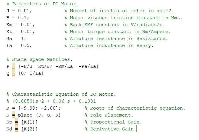
Using Matlab we get the value of Kp & Kd.
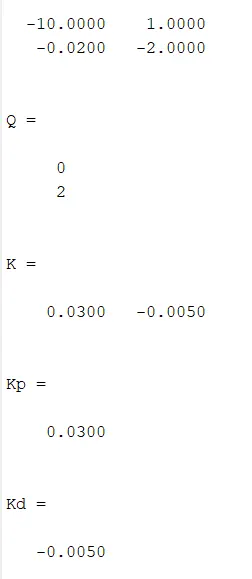
DC Motor Design
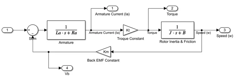
Simulink Model
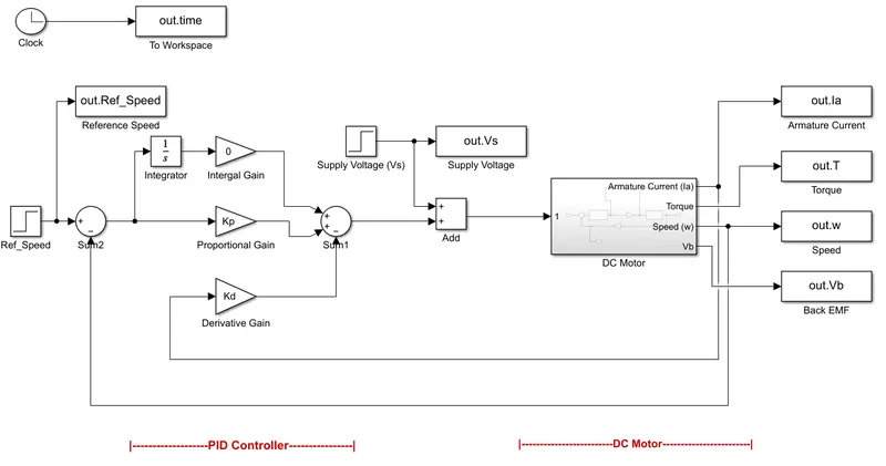
OBSERVATION :
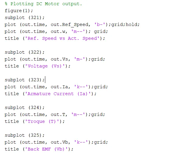
Matlab Plotting Commands.
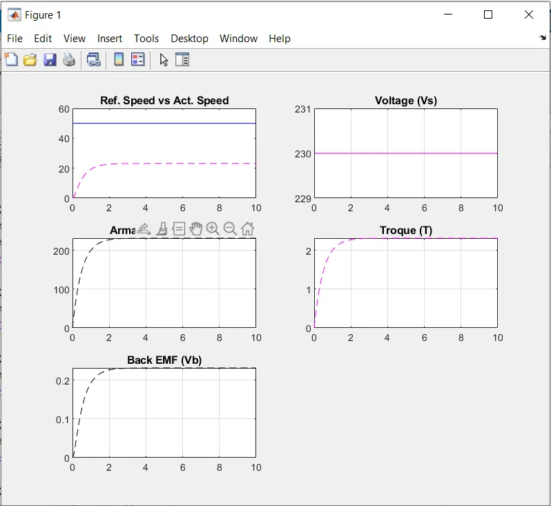
1 - Ki = 0. i.e. Integral Gain.
Actual speed is barely able to keep up with the reference speed of 50.
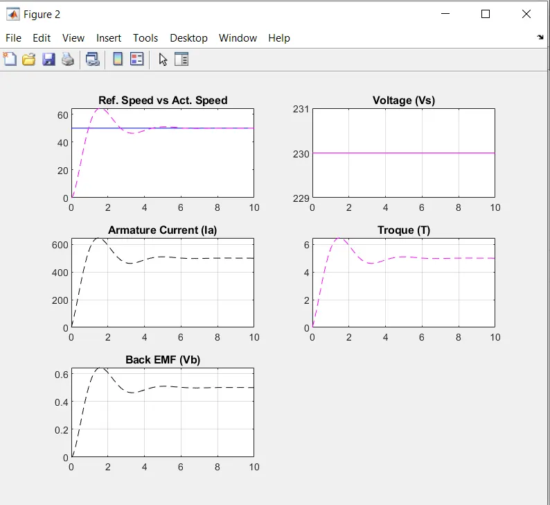
2- Ki = 20.
By increasing Ki we see overshoot and undershoot in response.
3- Ki = 5.
As we reduce the Ki drastically the motor reaches steady state without any overshoot and undershoot, but the rise time increases making the response sluggish.
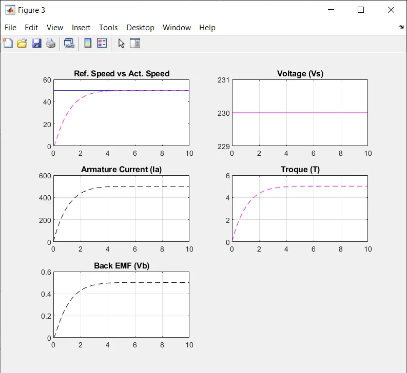
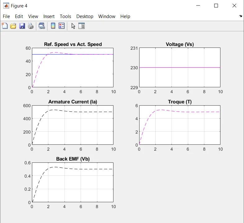
4- Ki = 8.
Slightly increasing the Ki although we get overshoot which is within tolerance, we see reduction in rise time and response becomes faster.
CONCLUSION :
With optimum values of Ki = 8, Kp = 0.03, Kd = -0.005, desired speed of motor is maintained with settling time, Overshoot & steady state error well within tolerance range.