Challenge: DC Motor Control
AIM:
The aim of this project is to study and evaluate different DC motor control.
OBJECTIVE 1: Run MATLAB demo ‘Speed control of a DC motor using BJT H-bridge’. Modify the model such that armature current doesn’t shoot up when motor changes direction from forward to reverse.
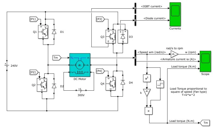
240V is source voltage to run the motor
The rated parameters of the DC motor used are 5HP,1750rpm
THE model consist of 4 BJT switches namely Q1,Q2,Q3,Q4. The Bipolar Junction Transistor (BJT) when used for power switching applications, operates as an IGBT. When it is conducting (BJT operating in the saturated region), a forward voltage Vf is developed between collector and emitter (in the range of 1 V). Therefore, the IGBT block can be used to model the BJT device
SIMULINK MODEL:
RESULTS:
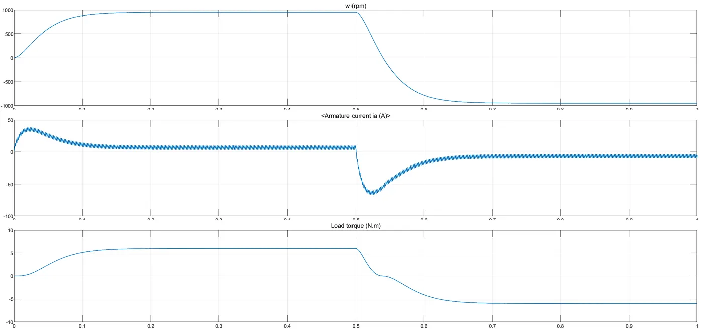
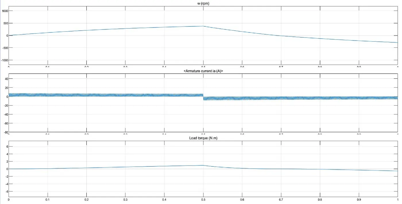
The motor starts in the positive direction with a duty cycle of 75% for 0.5 sec. After that armature voltage is suddenly reversed and the motor runs in the negative direction.
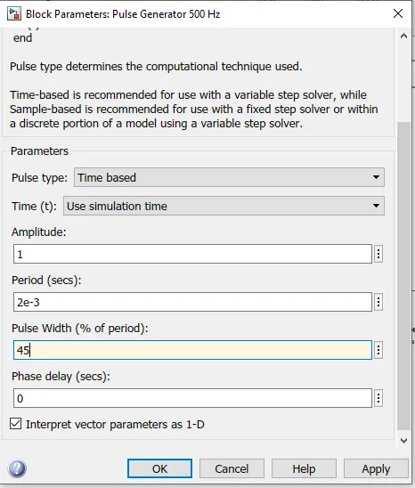
In order to avoid the armature current shoot up chnage the pulse width from 75% to 40%.
OBJECTIVE 2: Refer to help section of ‘The Four-Quadrant Chopper DC Drive (DC7) block’. Compare it with H-bridge model.
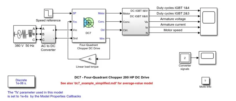
THE FOUR- QUADRANT CHOPPER DC DRIVE:
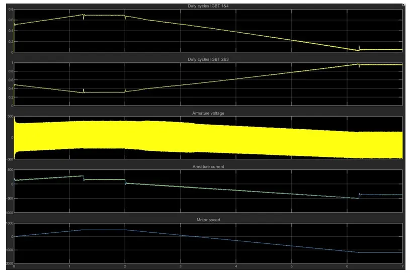
RESULT:
DC Motor BJT H Bridge block:
To change the direction of motor only the polarity of the current is changed
Forward and reverse motoring are the only two operations that tha H Bridge can perform
The current values are continuous
Regenerative braking is not possible but dynamic braking can be achieved.
4-Quadrant DC7 Chopper block:
To change the direction of motor signal are interrupted with one another.
It has four modes forward motoring ,reverse motoring Forward braking and reverse braking.
The current values are chopped not continuous hence simulation takes less time.
Regenerative braking is possible.
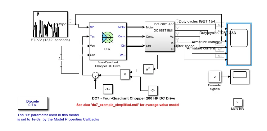
OBJECTIVE 3: Make a suitable EV model using DC7 block and make result report
RESULTS:
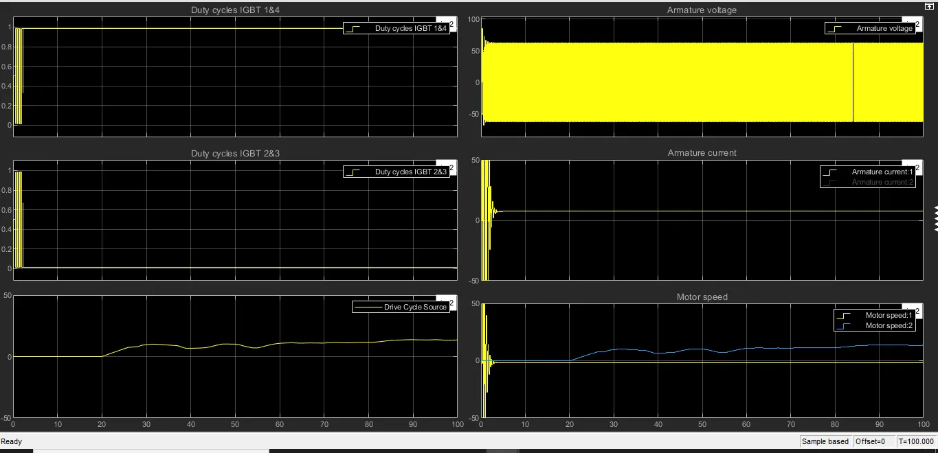
By observing the plot the motor speed varies according to the drie cycle