Week-7 Challenge: DC Motor Control
Note- THis is Live EV Batch 21.
Ans-1(A + B)-
BJT H-Bridge-
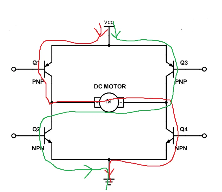
A H-bridge contains four transistor for switching action,and a load in the centre,which look like in 'H shape'.
A H-bridge is an electronic circuit that switches the polarity of a voltage applied to a load. This circuit is offently used in robotics to control the motor action as clockwise and anticlockwise rotation.It is also used in inverter.
When the positive signal is given,The switches Q1 and Q4 will active and the path of the current show by red colour.in this condition motor will run in clockwise or forward.At this time Q3 and Q2 will be in off condition.We can not trigger two switches in same side to protect the circuit.
When Q3 and Q2 are triggered ,the current path is shown by green colour.In this condition motor will run in reverse or anti clockwise direction.At this time Q1 and Q4 will be in in OFF .
Simulink Model of Speed control of a DC motor using BJT H-bridge-
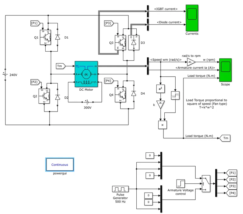
In this model H bridge is used to control the speed of motor.When BJT is used for switching action ,it operates as Insulated gate bipolar transistor(IGBT).The DC motor,used in the model is 5HP 24V 1750RPM.It simulate fan type load where load is proportional to square of speed.The armature voltage cab be varried from 0 to 240V when the duty cycle is varied from 0 to 100%.
Here we can observe that the input signal of IGBT is coming through P1,P2,P3,and P4 at the gate terminal.This p is controlled through the pulse generator.
In the operation,at a time only two BJT is triggered (either Q1 and Q4 or Q2 and Q3) .
Q1 and Q4 is used as forward motoring and Q3 and Q4 is used as reverse motoring.
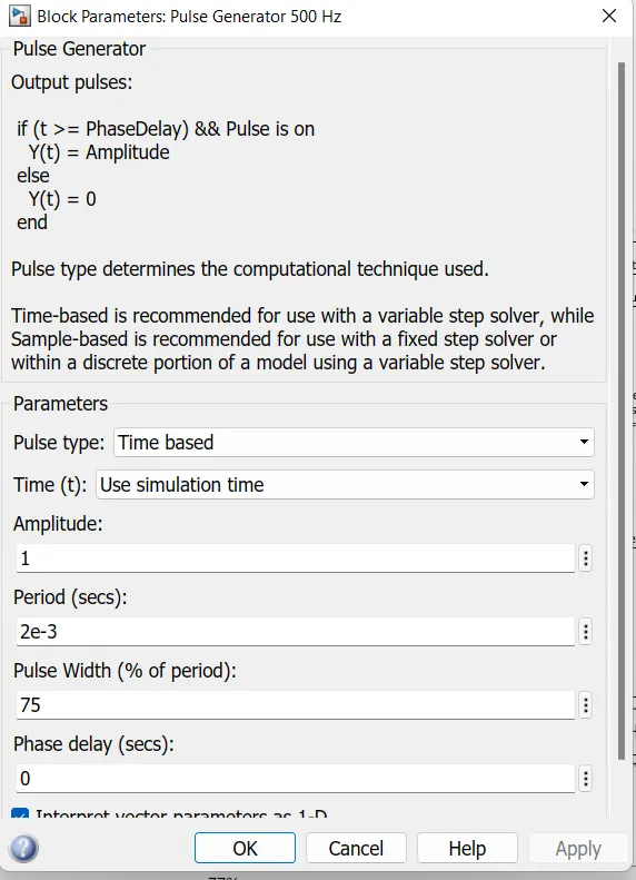
The pulse generator parameter is as follows-
The result is as below-
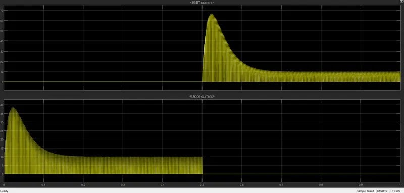
From above graph we can conclude that from 0 to 0.5sec ,IGBT current is zero whole there is obtain the diode current and after 0.5sec to 1sec we obtain IGBT current and diode current will be zero.

From above graph,we can see that there is sudden change in armature current,that is known as shoot-up.It can be change by changing the duty cycle.This is optained with 70% duty cycle.
For Duty Cycle 60%-
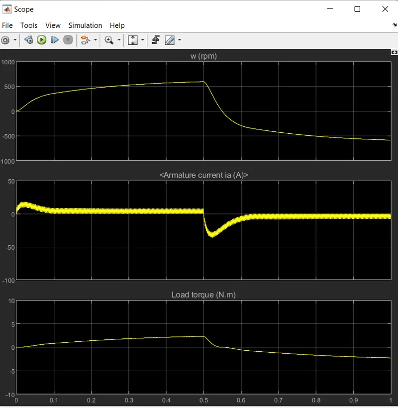
For Duty Cycle 50%-
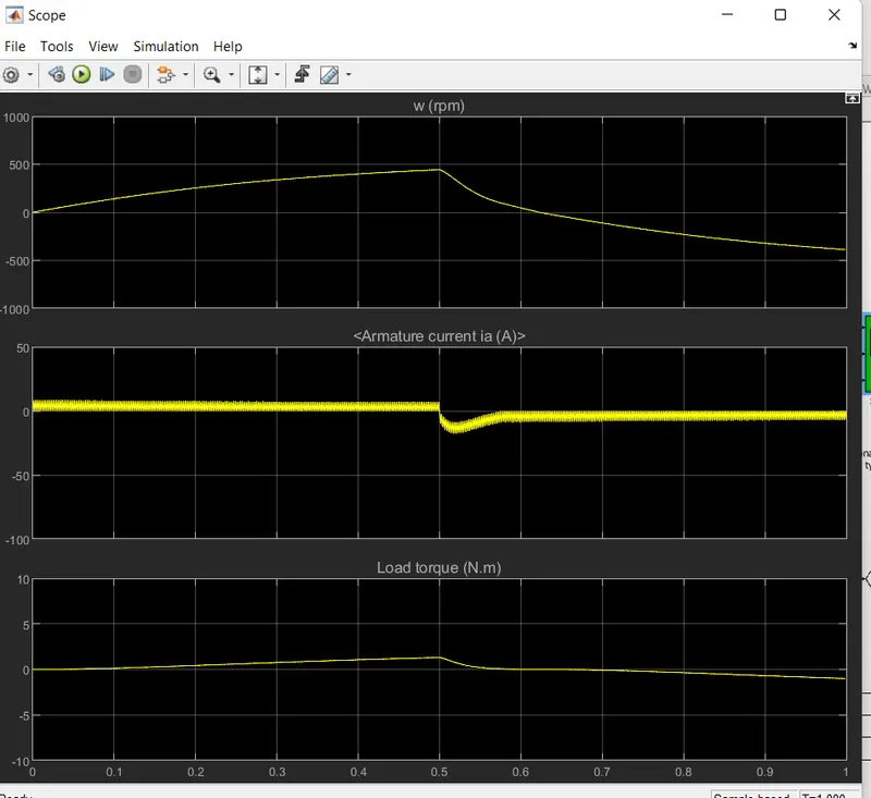
For Duty Cycle 40%-
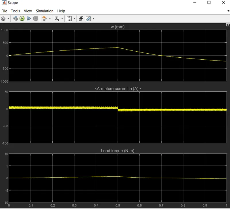
As we can observe that by increasing the Duty cycle,load torque decress and armature current also decreases.But we are not getting over shoot up.It is going smooth curve.So by decreasing the duty cycle ,the shoot up can be controled.
Ans-1(c):-
Comparison between The Four-Quadrant Chopper DC Drive and H bridge-
- The Four-Quadrant Chopper can be operate in all four modes(Forward motering,Forward braking,Reverse motering,Reverse braking,while H bridge operatesin onlt two mode that is Forward and Reverse Mode.
- In Four-Quadrant Chopper ,PID controller is used while in H bridge,No PID controller is used.
- Regenrrative breaking can be possible in Four-Quadrant Chopper but in H bridge ,it is not possible.
- The Four-Quadrant Chopper signal is discrete while H-bridge,signal is continuous.
- The Four-Quadrant Chopper is widly used in automobile sector to control the speed of motor while H bridge is widly used in robotics.
- The Four-Quadrant Chopper provide better efficiency and high power while H bridge provide modrate power.
Ans-3:-
BLDC Motor(Brushless DC motor)-
A brushless DC motor (BLDC) is a permanent magnet synchronous electric motor which is driven by direct current (DC) electricity and it accomplishes electronically controlled commutation system (commutation is the process of producing rotational torque in the motor by changing phase currents through it at appropriate times) instead of a mechanically commutation system. BLDC motors are also referred as trapezoidal permanent magnet motors.
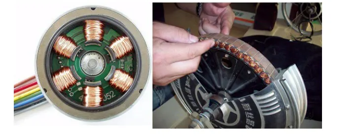
Construction of BLDC Motor-
The construction of this motor has many similarities of three phase induction motor as well as conventional DC motor. This motor has stator and rotor parts as like all other motors.
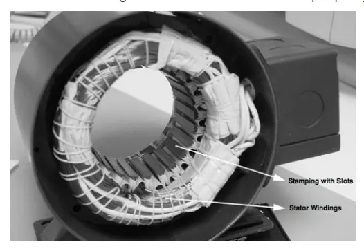
Stator of a BLDC motor made up of stacked steel laminations to carry the windings. These windings are placed in slots which are axially cut along the inner periphery of the stator. These windings can be arranged in either star or delta. However, most BLDC motors have three phase star connected stator.
Each winding is constructed with numerous interconnected coils, where one or more coils are placed in each slot. In order to form an even number of poles, each of these windings is distributed over the stator periphery.
Rotor
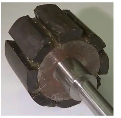
BLDC motor incorporates a permanent magnet in the rotor. The number of poles in the rotor can vary from 2 to 8 pole pairs with alternate south and north poles depending on the application requirement. In order to achieve maximum torque in the motor, the flux density of the material should be high. A proper magnetic material for the rotor is needed to produce required magnetic field density.
Working Principle Of A BLDC Motor
Stator windings of a BLDC motor are connected to a control circuit (an integrated switching circuit). The control circuit energizes proper winding at proper time, in a pattern which rotates around the stator.
The rotor magnet tries to align with the energized electromagnet of the stator, and as soon as it aligns, the next electromagnet is energized. Thus the rotor keeps running.
Commutator helps in achieving unidirectional torque in a typical dc motor.
Obviously, commutator and brush arrangement is eliminated in a brushless dc motor. And an integrated inverter/switching circuit is used to achieve unidirectional torque.
That is why these motors are, sometimes, also referred as ‘electronically commutated motors’.