Final Project: Design of an Electric Vehicle
Create a MATLAB model of electric car which uses a battery and a DC motor. Choose suitable blocks from Powertrain block set. Prepare a report about your model including following:
Objectives:
1. System level configurations
2. Model parameters
3. Results
4. Conclusion
Objective : To find the performance parameters of the designed model and make a report considering System level configurations, Model parameters, Results and make a Conclusion out of it.
Introduction :
Electric Vehicles (EVs) are the vehicles which operate only on stored electricity, and their main components consist of a high-voltage battery, one or more electric motors (either alternating current [AC] or direct current [DC]), and a controller to manage the power electronics.
Considering the main components of the EVs, the overall block diagram can be given as,
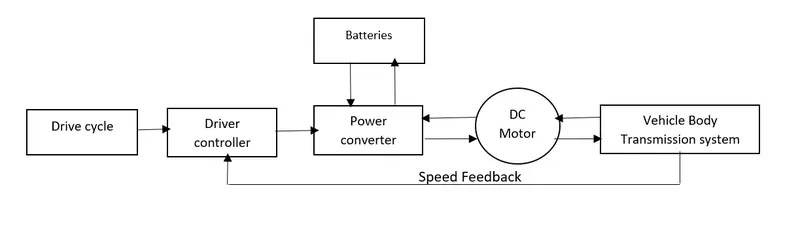
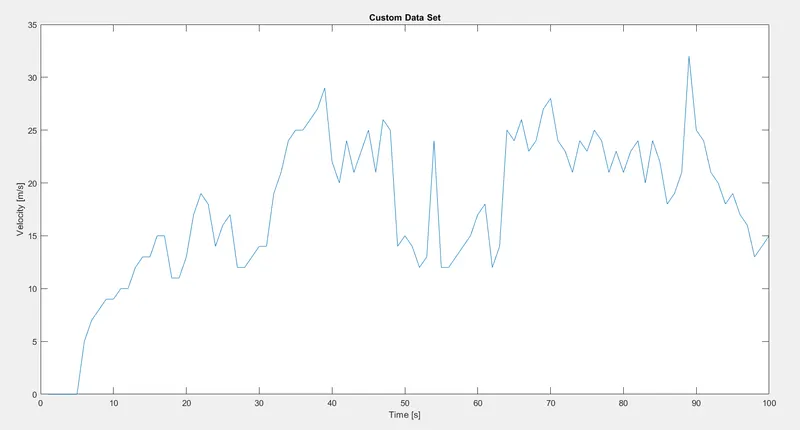
- Drive cycle : It is the data set of vehicle speed with respect to time. Here, for this model an Exel file created to be used as a drive cycle defining speed in m/sec with respect to each sec for 100 sec.
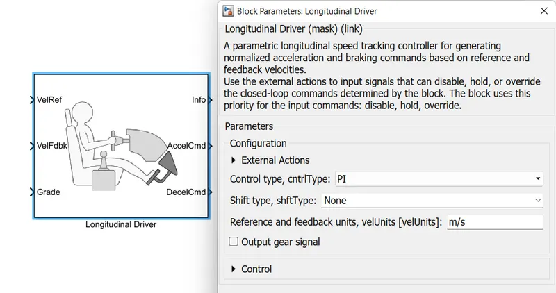
- Driver Controller : This is the block where we give drive cycle data as reference desired input and is compared to the feedback actual speed obtained. Then accordingly acceleration or deceleration signal is given.
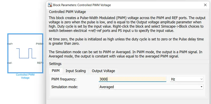
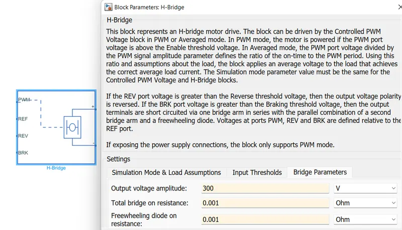
- Power converter : This is a power electronic circuit which converts electrical power as DC-DC or DC-AC and delivers the necessary power as required. Here, DC motor is used, so we required only DC-DC converter which will convert battery supplied voltage and deliver to the motor and other systems associated.
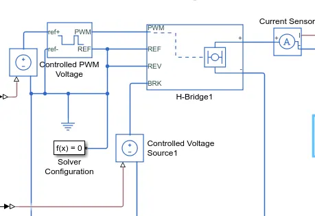
in the model, converter consists of Controlled PWM voltage block and a H-bridge block,
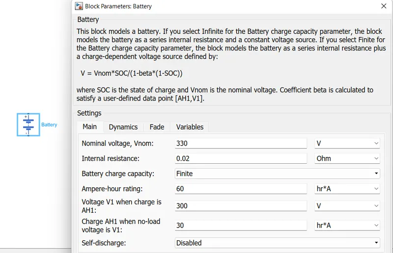
- Battery : This is the source of power for the EV. These are High capacity energy storage devices which supplies all the required power for the different systems via power converter controlled circuit.
here the battery block is used with the parameters as,
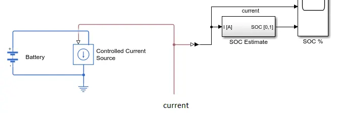
This is connected to a SOC estimate subsytem, to continuously observe the battery performance i.e. state of charge of the battery over the period of time according to the usage.
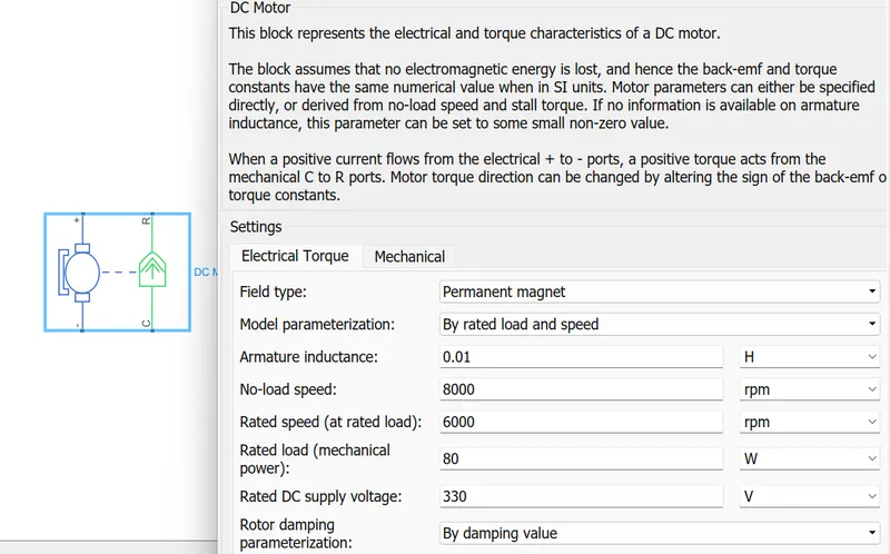
- DC motor : Here permanent magnet DC motor is used with the parameters as,
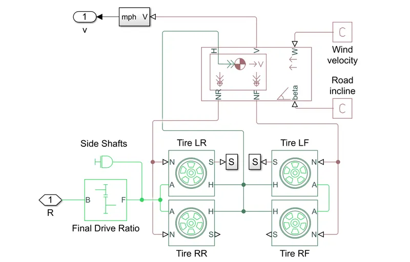
- Vehicle body and Transmission system : This is a subsystem consists of Vehicle body associated with wheels with drive ratio and shaft system. here, for vehicle body, mass, wind velocity and road angle of inclination these parameters are to be given as input variables and as output reaction force acting on tires are obtained. Also we can set parametes for tires as well. The subsystem can be designed as,
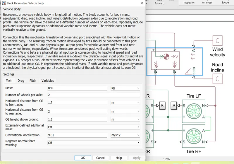
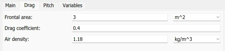
Parameters for the vehicle body can be given as following,
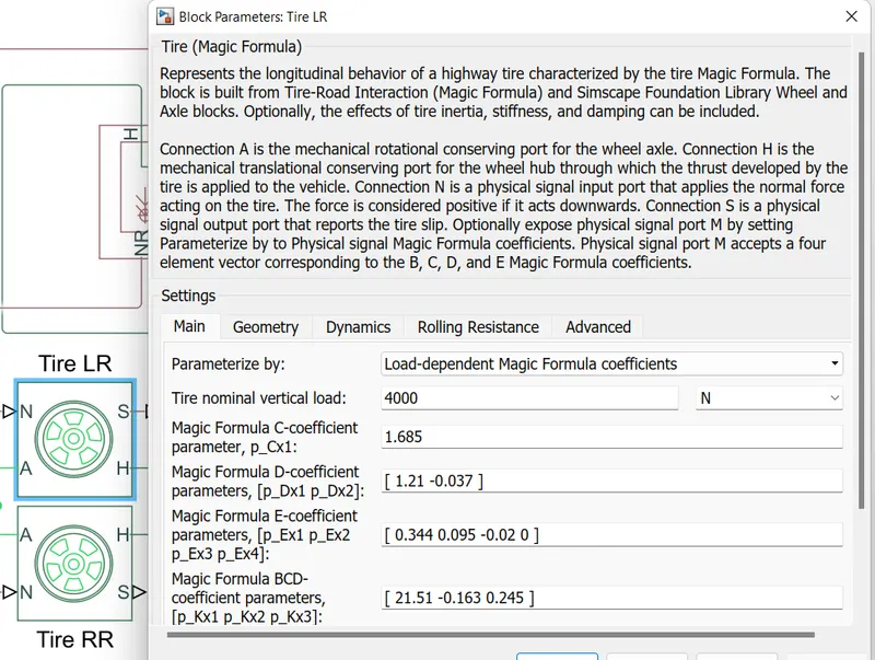
Also for the tires,



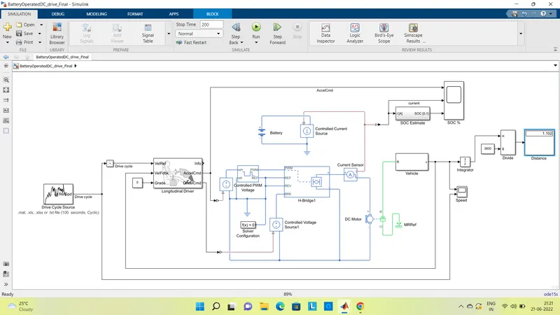
With all these blocks and parameters, the model can be designed as,
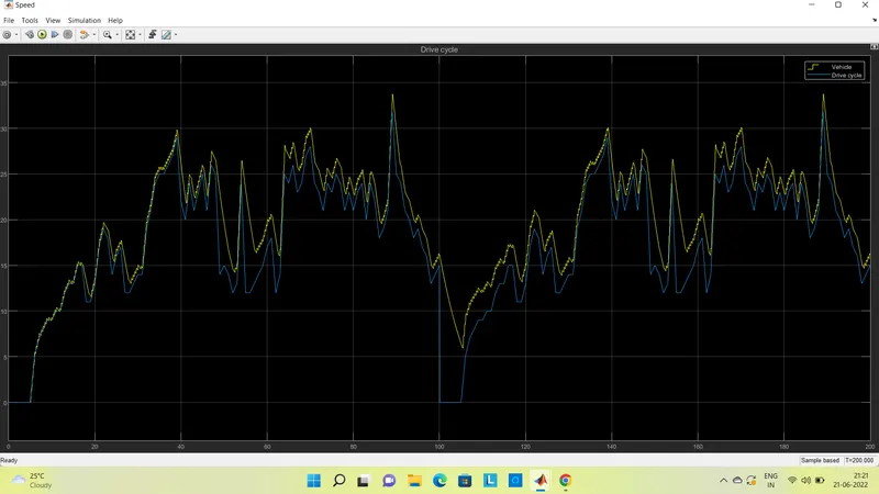
Results obtained for the simulation time of 200 sec,
- drive cycle and actual vehicle speed :
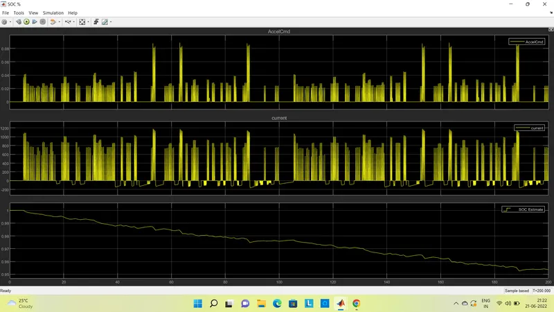
- Acceleration signal, Current supplied and SOC of battery :
- Conclusion :
With respect to this model, actual speed obtained by the vehicle is almost as same as input drive cycle, but not exactly same as it depends on the battery capacity selected and associated motor. Distance covered by the vehicle is displayed in the connected display i.e. in 200 sec with given parameters vehicle will travel distance of 1.09 km and will keep on increasing with increase of simulation time and may differ with ulterations of parameters.
Also, SOC % of the battery after simulation of 200 sec is 95 %. so, the vehicle can run on same drive cycle over the large period of time until the SOC % becomes 0. Also, in this model, regerative braking is enabled, so whenever the is decelaration of the vehicle, power is being fed back to the battery And SOC % is increasing for that period.
In this way, for different drive cycles, and various parameters, electric vehicle model can be designed and the performance of the vehicle can be analysed.