Week-7 Challenge: DC Motor Control
1A. Explain a MATLAB demo model named ‘speed control of a DC motor using BJT H-bridge.
BJT H-Bridge
In general, an H-bridge is a rather simple circuit, containing four switching elements, with the load at the centre, in a H-like configuration.
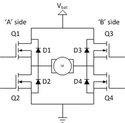
Fig showing the H-bridge with MosFETs
The Switching elements in the H- bridge are usaiily Bi-polar or FET transistors, in some high-votage applications IGBT’s. The diodes used in the H-bridge are called catch diaodes and are usually of a Schottky type.
Description
The Bipolar junction Transistor (BJT) when used in power applications, operates as IGBT, it is like a combination of MOSFET and BJT. When it is conducting a forward voltage Vf is developed between collector and emitter (in the range of 1V). Therefore, the IGBT block can be used to model the BJT device.
The IGBT block does not simulate by the gate current controlling the BJT or IGBT. The switch (IGBT) is controlled by a Simulink signal either 1 or 0.
Construction
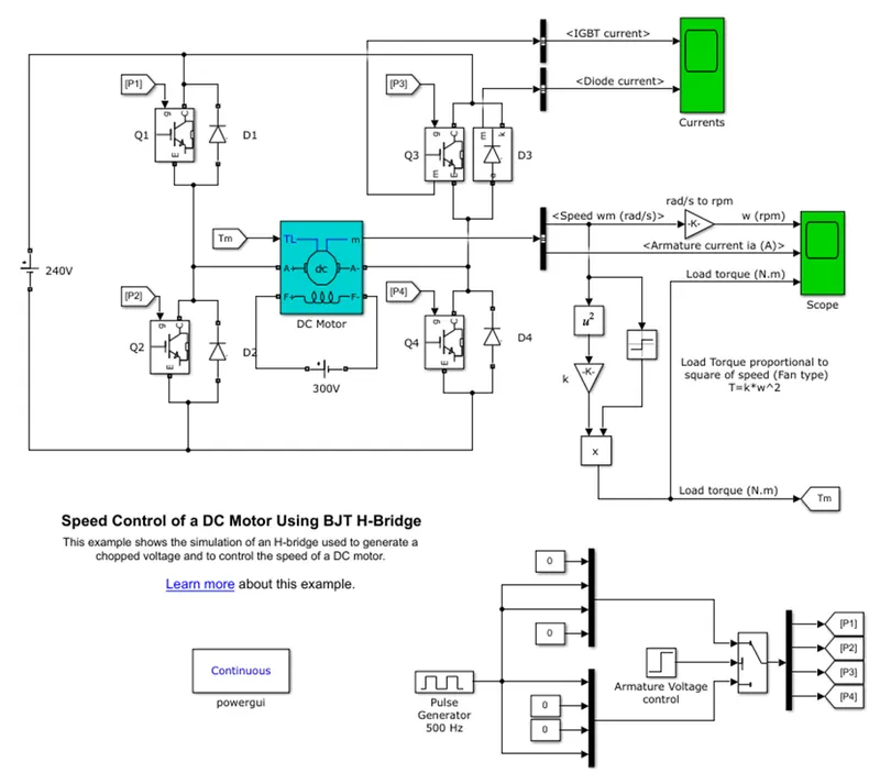
To construct H-bridge chopper circuit used four IGBT’s with anti-parallel diodes. DC motor load is connected in between the switching elements in a fashion that forms the H-bridge. Configuration of DC motor uses the pre-set model 5HP,24V,1750rpm and mechanical input given as toque load which is proportional to square of speed. Wound type field is selected and which is separately excited by 300V constant DC voltage source. H-BRIDGE chopper circuit fed by DC voltage source with given amplitude 240V. which means armature voltage can be varied from 0 to 240V when the duty cycle is varied from 0 to 100%. Duty cycle is given using pulse generator block.
Model
Working
- In the above circuit, the input voltage is generated from the pulse generator where the amount of supply and duty cycle is assigned in the pulse generator.
- Then the switch block is connected to pulse generator through an armature voltage control block.
- In this model to construct the H-bridge we have used 4 IGBT’s with 4 Diodes in antiparallel manner.
- The two IGBT’s (Transistors) are switched simultaneously at a time Q1 and Q4 or Q2 and Q3 are switched at a time.
- When Q1 and Q4 are fired, a positive voltage is applied to motor and Diodes D2-D3 operate as free -wheeling diodes when Q1 and Q4 are switched OFF.
- When Q2 and Q3 are fired, a negative voltage is applied to motor and Diodes D1 and D4 acts as free-wheeling diodes when Q2 and Q3 are switched OFF.
- A switch block at the bottom of the circuit splits the power supply in to 4 parts namely p1, p2, p3 and p4.
- The DC motor is connected to a battery, and the DC motor’s mechanical input is initiated as Torque.
- Torque for a mechanical input of DC motor also switched by goto and from.
- The output of the DC motor is connected with the Bus selector where we can choose our desired results from the motor.
- In this we choose Speed of the motor that is in rad/sec that is again in turn converted to RPM and Armature current of the motor from the bus selector.
Result
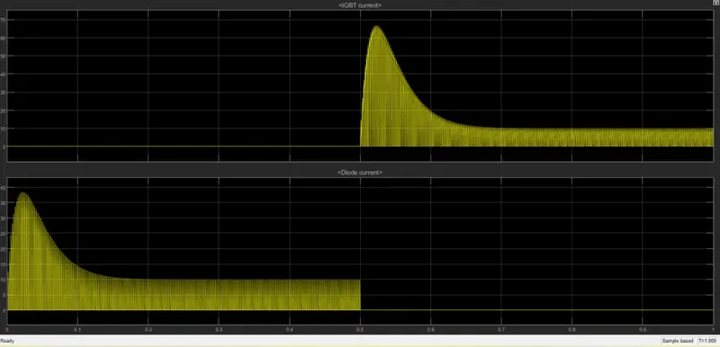
Fig showing the scope result of IGBT and Diode Currents
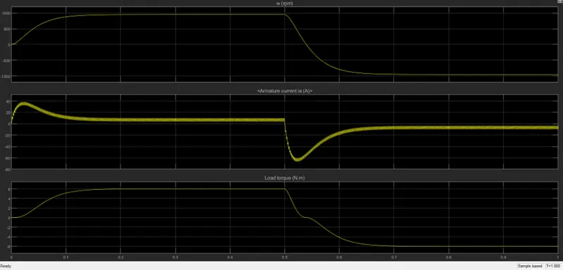
Fig showing the scope result of Speed, Armature Current and Load Torque of the motor
Observation
The motor starts in the positive direction from t=0 to 0.5secs with a duty cycle of 75% and gets average output voltage of 180V. At t=0.5 sec., the armature voltage suddenly reversed and the motor runs in the negative direction.
1B. Comment on the armature current shoot up from the scope results.
- From the armature current graph, we can observe that from T=0 secs to T=0.5 secs armature current is positive and at T=0.5 secs current direction is reversed so, it is negative.
- At the time of starting from 0 sec to 0.05 secs armature current is reaches to its positive peak value around 36A and settled at around 10A up to 0.5 secs.
- My comment is that as there is no Back Emf (Eb) present in the motor at starting as speed of the motor is zero that is speed of the motor is directly proportional to the Back Emf and the armature current Ia=(V-Eb)/Ra the armature current will be high at the starting of the motor.
- When it reversed it reaches to its negative peak value is around 65A and after sometime settled at around -7A.
- From the graph we can observe that at the staring current is high for few milli seconds and it is also high for few milli seconds when the voltage is reversed.
1C. Refer to the help section of ‘The Four-Quadrant Chopper DC Drive (DC7) block’. Compare it with the H-bridge model.
Chopper
Chopper is a static switch used to obtain the variable dc voltage from a source of constant dc voltage. If the average output voltage is less than the input voltage than the chopper is called step-down chopper. If the average output voltage is greater than the input voltage than the chopper is called step-up chopper.
Four-Quadrant Chopper DC Drive (DC7) block
Model
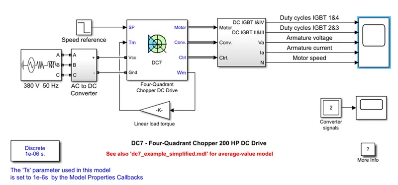
DESCRIPTION:
Three phase source is used for the AC supply, ph-ph rms voltage is given 380V at 50Hz frequency. Three phase ac supply is converted to DC by using bridge rectifier. In order to limit the DC bus voltage during dynamic braking mode, a braking chopper has been added between the diode rectifier and the DC7 block.
The Four-Quadrant Chopper DC Drive (DC7) block represents a four-quadrant, DC-supplied, chopper (or DC-DC PWM converter) drive for DC motors. This drive features closed-loop speed control with four-quadrant operation. The speed control loop outputs the reference armature current of the machine. Using a PI current controller, the chopper duty cycle corresponding to the commanded armature current is derived. This duty cycle is then compared with a sawtooth carrier signal to obtain the required PWM signals for the chopper.
The main advantage of this drive, compared with other DC drives, is that it can operate in all four quadrants (forward motoring, reverse regeneration, reverse motoring, and forward regeneration). In addition, due to the use of high switching frequency DC-DC converters, a lower armature current ripple (compared with thyristor-based DC drives) is obtained. However, four switching devices are required, which increases the complexity of the drive system.
Selector block subsystem is created to take the required output signal by using bus link and armature voltage, armature current, speed, duty cycles of IGBT 1 & 4 and duty cycles of IGBT 2 & 3 are connected to scope.
Comparison:
|
Four-Quadrant Chopper |
H-bridge model |
|
With the Four-Quadrant chopper model the motor can be operated in four different modes (forward motoring, reverse motoring, forward braking, reverse braking). |
In this model we can operate only in two modes by changing the direction of motor i.e., forward and reverse. |
|
Regenerative braking can be achieved with this model. |
No regenerative braking can be achieved. |
|
The signals given to four switching devices (choppers) are discrete. |
Here the signals are continuous. |
|
The Four-Quadrant chopper model was widely used in the automobile application for the control of DC motor speed and direction. |
The H-bridge is used in the robotics and electro-mechanical devices to control the speed and direction of DC motor at low level speed. |
2) Develop a 2-Quadrant Chopper using Simulink & explain the working of the same with the relevant results.
Aim: To develop a 2-Quadrant Chopper
Objective: To develop a 2-Quadrant Chopper using Simulink and explain the working of the same with the relevant results.
Description:
2-Quadrant Chopper: Based on the operation of chopper in the quadrants the 2-Quadrant chopper is of two types.
- Class C or Type A chopper
- Class D or Type B chopper
Class C or Type A chopper
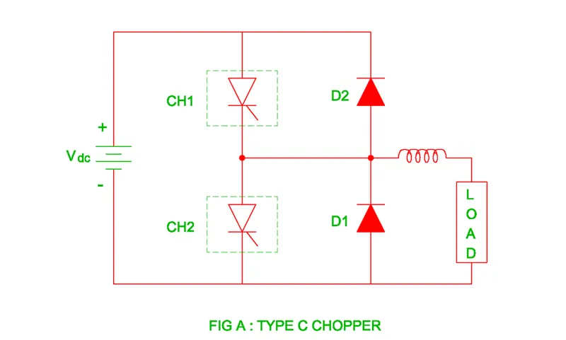
Class C chopper is obtained by connecting Class-A and Class-B choppers in parallel. We will always get a positive output voltage V0 as the free-wheeling diode FD is present across the load.
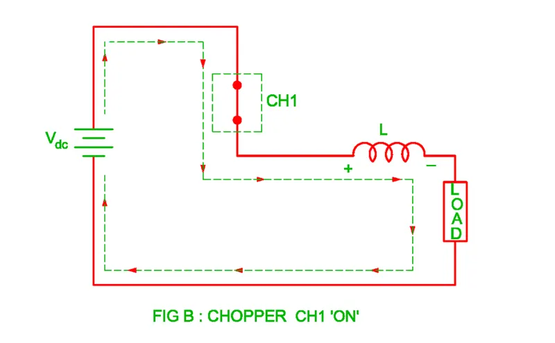
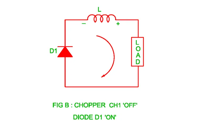
When the chopper CH-1 is ON load current i0 flows from source to the load that is i0 is positive and the inductor current increases exponentially. when the chopper CH-1 is off the free-wheeling diode conducts and current continuous to flow in the same direction through the freewheeling diode as the inductor doesn’t allow sudden change in current but the voltage will be zero this means the voltage may be positive or zero and the current is positive during CH-1 and FD operation. This acts as Class A chopper.
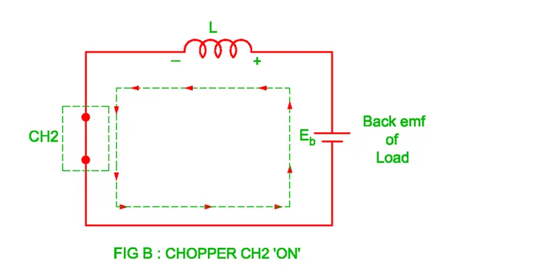
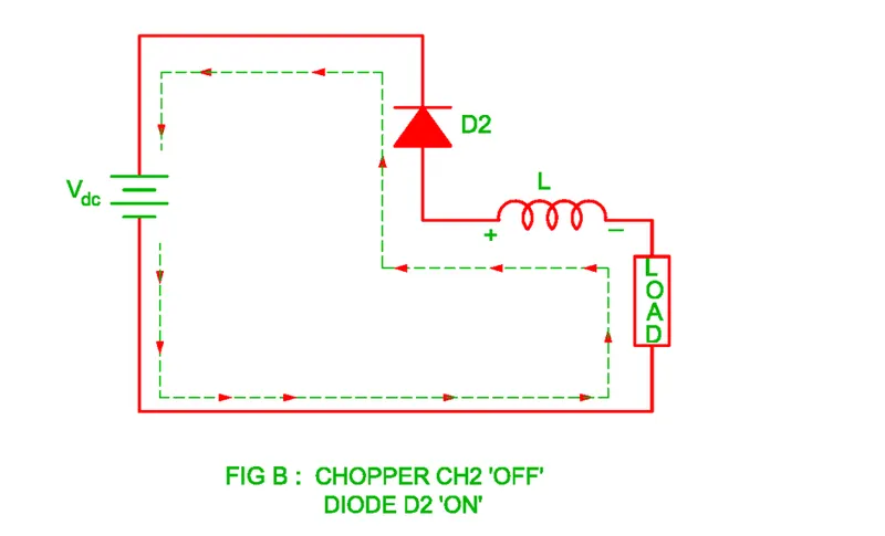
Then the chopper CH-2 is switched ON due to the back emf of DC motor, The load current flows in the negative direction through the path Load – Inductor - CH-2 – Load. The negative current flows until chopper CH-2 is switched OFF and chopper CH-1 is switched ON. When the chopper CH-2 is switched off, the stored energy of inductor dissipates its energy through path L – D2 – Vs – Load – L. This acts as Class B chopper.
When chopper CH-1 or diode FD conducts, the load current becomes positive and load current becomes negative when CH-2 or D2 conducts. The chopper CH-1 and CH-2 never conducts simultaneously otherwise the DC supply source is short circuited.

Class D or Type B chopper
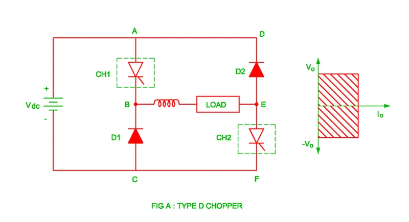
The two quadrant Type B chopper or Class D chopper works is first as well as the fourth quadrant therefore the output current remains positive but output voltage may be either positive or negative. The polarity of output voltage depends up on the chopper ON time and chopper OFF time. When TON > TOFF – Output Voltage Positive, TON > TOFF – Output Current Negative TON = TOFF – Output Voltage Zero.
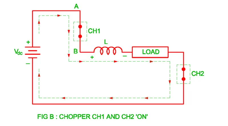
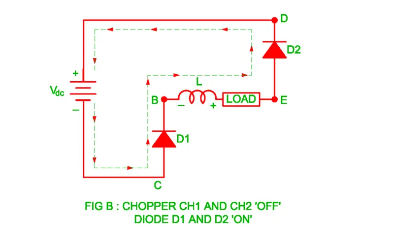
When Chopper CH-1 and CH-2 both are switched on simultaneously, the current flows through the path (+) Vdc - CH-1 – Load – CH-2 – Vdc (-). The voltage across load is equal to the supply voltage Vdc and current increases exponentially. The chopper works is first quadrant because the output voltage and output current both are positive.
When chopper CH-1 and CH-2 both are switched OFF simultaneously, the Diode D1 and D2 forward biased and current flows through the path Load – D2 - (+) Vdc -Vdc (-) – D1. The chopper works in the fourth quadrant because the output voltage negative and output current positive. The application of Class-D chopper is in the forward motoring and regenerative braking of motor.
MODEL:
- As there are two types of 2-Quadrant Choppers i choose the Class-D type Chopper in this simulation
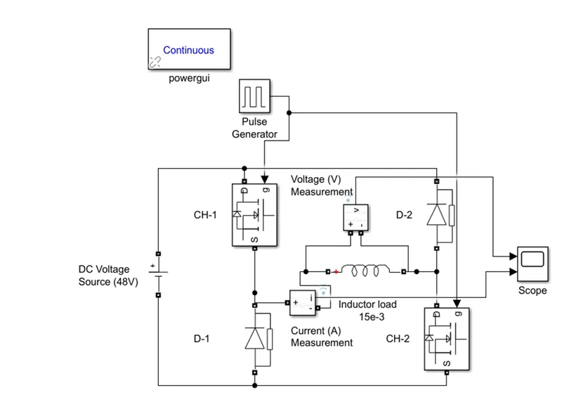
Fig showing the simulink model of 2-Quadrant Class-D chopper
Google Drive Link for Two Quadrant Chopper
https://drive.google.com/file/d/1z_qaA_7FnwxFR_zddAN8ax8pqzrv1o8t/view?usp=sharing
Blocks Used
The Blocks used in this model are
- Powergui (Continuous)
- Pulse Generator
- DC Voltage Source
- MOSFET
- Diode
- Series RLC branch
- Current Measurement
- Voltage Measurement
- Scope
Construction
- In this model we have taken the DC supply voltage source as 48V.
- We have used two choppers and two diodes and a series RLC branch to build the circuit.
- The Choppers and Diodes in such a manner that the load will be in between the two Choppers and also it should be in between the two Diodes as well.
- The signal to gate pulses of choppers was given from the pulse generator.
- The Amplitude of the pulse was chosen to be 10 and period was taken as 0.04sec (1/f = 1/25) such that 25 pulses will be given to the gates of MOSFETS in a second.
- The pulse width % was taken as 50 that means the choppers will be ON for 50% of time period and Diodes will be forward biased for another 50%.
- The Current measurement block was connected in series with the Inductor Load and the Voltage measurement block connected in parallel.
- Here the inductor load was taken as 15e-3H.
- I choose the simulation time for 1s.
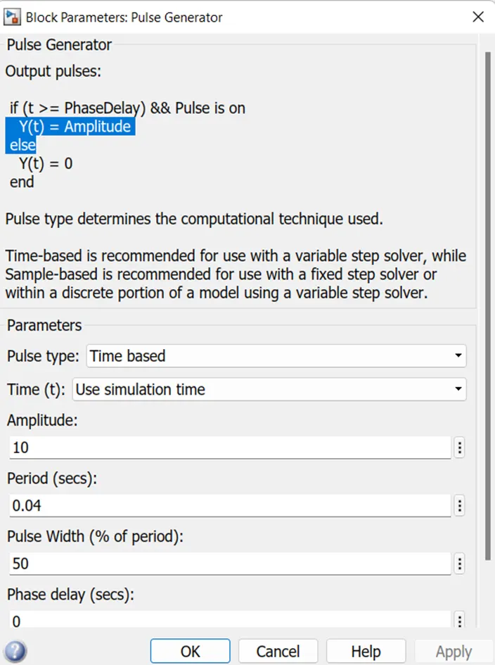
Fig showing the Block Parameters of Pulse Generator
Working
- The working of Class-D type chopper is simple, when there is pulse input signal the two Choppers CH-1 and CH-2 gets ON simultaneously.
- When the two choppers are in ON condition the load current flows from source to the load.
- Then the voltage across the load will be equal to the supply voltage and the current in the inductor load increases exponentially, as the inductor stores the energy.
- The current and the voltage will be positive in this period.
- After 50% of the Time period the pulse from the Pulse generator will become Zero then both the choppers will be in OFF state.
- When the two choppers are in OFF state then the as the inductor gets de-energized and current flows from Load to Source in this period the current will be positive but the voltage will be negative.
Results:
- From the scope we got the results
- By observing the current waveform, we can say that the load current is positive in both the quadrants.
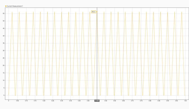
Fig showing the current across the load of 2-Quadrant Class-D chopper
- By observing the voltage waveform, we can say that the voltage across the load may be positive, zero or negative
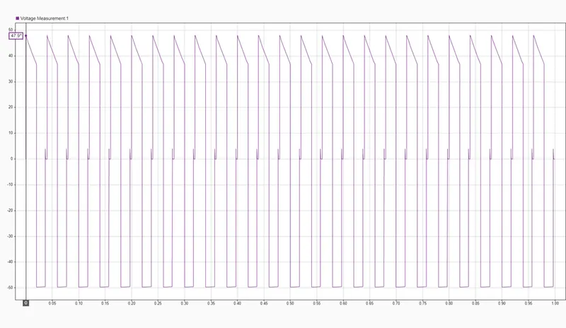
Fig showing the voltage across the load of 2-Quadrant Class-D chopper
3) Explain in brief about opertaion of BLDC motor
Brushless DC Motor (BLDC):
A brushless DC motor (also known as a BLDC motor or BL motor) is an electronically commuted DC motor which does not have brushes. The controller provides pulses of currentto the motor windings which control the speed and torque of the synchronous motor.
These types of motors are highly efficient in producing a large amount of torque over a vast speed range. In brushless motors, permanent magnets rotate around a fixed armature and overcome the problem of connecting current to the armature. Commutation with electronics has a large scope of capabilities and flexibility. They are known for smooth operation and holding torque when stationary.
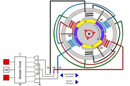
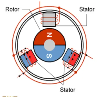
Operation:
BLDC motor works on the principle similar to that of a Brushed DC motor. The Lorentz force law which states that whenever a current carrying conductor placed in a magnetic field it experiences a force. As a consequence of reaction force, the magnet will experience an equal and opposite force. In the BLDC motor, the current carrying conductor is stationary and the permanent magnet is moving.
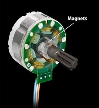
When the stator coils get a supply from source, it becomes electromagnet and starts producing the uniform field in the air gap. Though the source of supply is DC, switching makes to generate an AC voltage waveform with trapezoidal shape. Due to the force of interaction between electromagnet stator and permanent magnet rotor, the rotor continues to rotate.
With the switching of windings as High and Low signals, corresponding winding energized as North and South poles. The permanent magnet rotor with North and South poles aligns with stator poles which causes the motor to rotate.
Types of Brushless DC Motors:
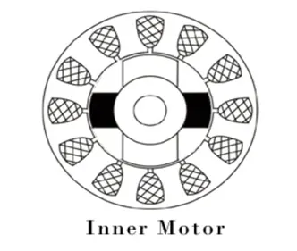
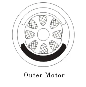
Basically, BLDC are of two types, one is Inner Rotor Motor and other is Outer Rotor Motor. The basic difference between the two is only in designing, their working principles are same.
Inner Rotor Motor:
In an inner rotor design, the rotor is located in the centre of the motor and the stator winding surround the rotor. As the rotor is located in the core, rotor magnets do not insulate heat inside and heat get dissipated easily. Due to this reason, inner rotor designed motor produces a large amount of torque and validly used.
Outer Rotor Motor:
In outer rotor design, the rotor surrounds the winding which is located in the core of the motor. The magnets in the rotor trap the heat of the motor inside and do not allow to dissipate from the motor. Such type of designed motor operates at lower rated current and has low cogging torque.
Advantages of BLDC Motor:
The advantages of a BLDC motor are:
- Brushless motors are more efficient as its velocity is determined by the frequency at which current is supplied, not the voltage.
- As brushes are absent, the mechanical energy loss due to friction is less which enhanced efficiency.
- BLDC motor can operate at high-speed under any condition.
- There is no sparking and much less noise during operation.
- More electromagnets could be used on the stator for more precise control.
- BLDC motors accelerate and decelerate easily as they are having low rotor inertia.
- It is high performance motor that provides large torque per cubic inch over a vast sped rang.
- BLDC motors do not have brushes which make it more reliable, high life expectancies, and maintenance free operation.
- There are no ionizing sparks from the commutator, and electromagnetic interference is also got reduced.
- Such motors cooled by conduction and no air flow are required for inside cooling.
Disadvantages of BLDC Motor:
The disadvantages of a BLDC motor are:
- BLDC motor costs more than a Brushed DC motor
- The limited high power could be supplied to BLDC motor, otherwise, too much heat weakens the magnets and the insulation of winding gets damaged.
Applications of BLDC Motor:
Brushless DC motors (BLDC) use for a wide variety of application requirements such as varying loads, constant loads and positioning applications in the fields of industrial control, automotive, aviation, automation systems, health care equipment’s etc.
- Computer hard drives and DVD/CD players
- Electric vehicles, hybrid vehicles, and electric bicycles
- Industrial robots, CNC machine tools, and simple belt driven systems
- Washing machines, compressors and dryers
- Fans, pumps and blowers.