Week -2
TASK-1
SIMULINK MODEL OF DOORBELL USING SOLENOID BLOCK
AIM: To model a Simulink model of ”Doorbell” using “Solenoid” block.
OBJECTIVE: For the model of doorbell using solenoid block we have to create a situation where a switch is closed for 2sec and then released and have to observe the physical movement of plunger assuming the other parameters.
THEORY:
Doorbell Mechanism Using Solenoid:
- Solenoid is a coil winding with a plunger attached to it.
- When current passes through it, it acts as electromagnet.
- In the doorbell mechanism the plunger is attached to a spring assembly inside the winding.
- When the current passes through the winding it acts electromagnet and generates magnetic field.
- The magnetic field that generated attracts the plunger and the plunger hits the bell.
- In the above mechanism as the plunger is attached to the spring assembly it restores to its original position after removing the supply to the solenoid.
MODEL:
https://drive.google.com/file/d/1v9amCs7kpe5CXC4DQzHOy76xtJhzEC63/view?usp=sharing
PROCESS:
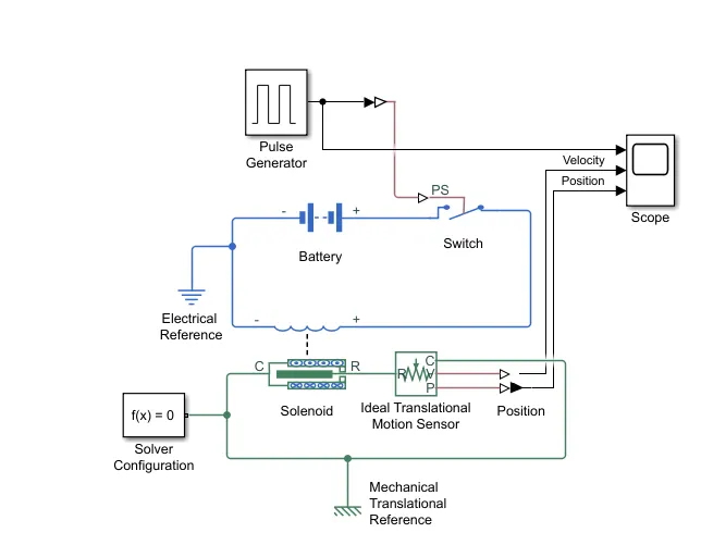
- In this model we have used battery as source to give supply to the solenoid.
- The Positive terminal of the battery is connected to the switch and from the switch the supply is given to one terminal of solenoid.
- The negative terminal of the battery is given to the other terminal of solenoid.
- In this model we have used pulse generator as trigger to the switch by keeping the block parameters as period of pulse for 4sec and pulse width of 50% and amplitude at 1 with phase delay at 0.
- To sense the motion of the plunger we have used ideal translational motion sensor.
OUTPUT:
OBSERVATION:
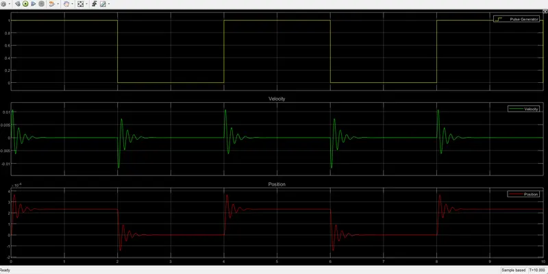
- After running the above model for run time of 10sec we can observe that the position and velocity of plunger was changed and came back to the original position after releasing the switch.
- We can observe the changes in scope.
TASK-2
SIMULINK MODEL TO SENSE THE TEMPERATURE OF A HEATER USING THERMISTOR
AIM: To model a Simulink model using ”Thermistor” to sense the temperature of a heater and turn on or turn off the fan.
OBJECTIVE: For the model mentioned above we have to create a situation where the temperature should be 20°C for 0-10sec 27°C for 10-30sec and 23°C for 30-50sec and need to turn on the fan when the temperature is above 25°C by sensing the temperature using thermistor or else turn off.
MODEL:
https://drive.google.com/file/d/1OKLA9bMjL2FCRqbq0944feTtK2j69JkE/view?usp=sharing
PROCESS:
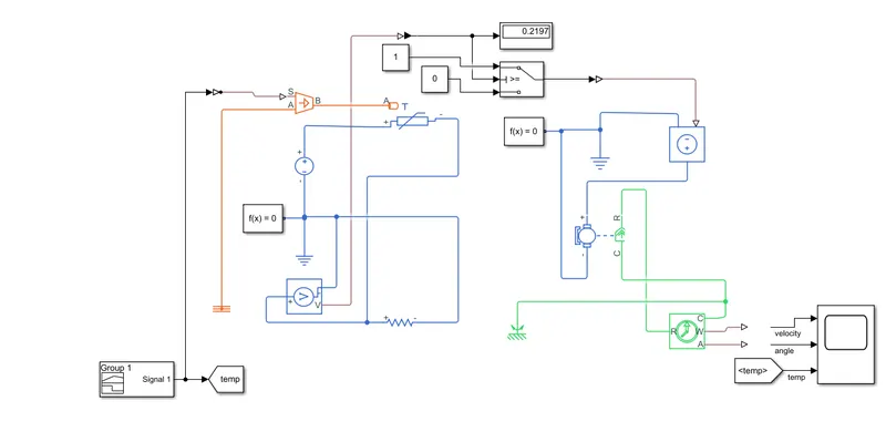
- In this model we have used signal builder block to generate signal for the given temperature conditions.
- In this model we have converted the °C temperature values to Kelvin values and modelled the desired signal in the signal builder as the thermal blocks cant sense the °C Values.
- We gave the output from the signal builder to the controlled temperature source as an input, The controlled source it maintains a controlled temperature difference regardless of the heat flow rate.
- From the controlled temperature source, we gave the input to the thermistor.
- In this model we used the resistor block along with the voltage sensor block which was connected in parallel to the resistor to sense the voltage across the resistor at 25°C.
- In this model we used coder/signal routing switch to on the fan if the temperature is above 25°C off otherwise by setting the threshold voltage as reference for 25°C.
- In this model we used controlled voltage source block to give supply to the dc motor.
- We used the dc motor as a fan in this model.
- To sense the velocity and angle of the dc motor/ fan with respect to the temperature condition we used the ideal rotational motion sensor.
OUTPUT:
OBSERVATION:
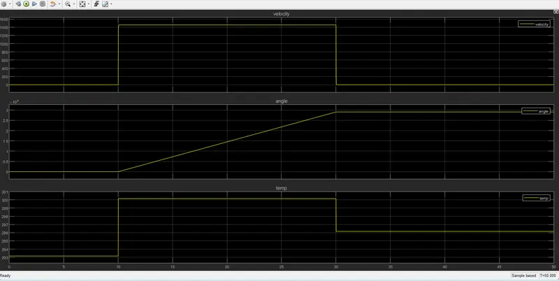
- After running the above model for run time of 50 sec we can observe that the dc motor/fan is only in ON condition when the temperature is 25°C and above and is in OFF condition when the temperature is below 25°C.
- We can observe ON & OFF Condition of fan by using the scope block.