Project
SYSTEM LEVEL SIMULATION OF AN ALL-TERRAIN VEHICLE
AIM: To Run a system level simulation of an “ALL TERRAIN VEHICLE”.
OBJECTIVE: To observe the speed and distance of a vehicle body by varying the throttle and brake and also to observe the relation between the primary and secondary shaft speed of a CVT for different CVT ratio.
DESCRIPTION:
CVT (CONTINUOUSLY VARIBLE TRANSMISSON): A continuously variable transmission system is a type of automatic transmission in which an arrangement of pulleys and belts made it possible for a drive to achieve n-number of continuous gear ratios within a range (depends on the design).
A continuously variable transmission in a vehicle senses the accelerator input with engine load and get shifted to the desired speed or torque gear ratio automatically, in other words we can say that a cvt transmission is one of the simplest types of automatic transmission that provides continuous uninterrupted power within a specified range of speed and torque ratios.
COMPONENTS OF CVT:
- Primary pulley
- Secondary pulley
- Variator
- Belt
WORKING: The Variator of the CVT which is connected to primary pulley when it goes outward, the variator of the secondary pully will move inward such that the radius of the secondary pulley will be more than the radius of the primary pulley so that will lead to speed reduction on the other hand when the variator of the primary pulley moves inward the variator the secondary pulley moves outward and it will lead to overdrive.
PROCESS:
- In this model we are analysing various parameters of BAJA ATV Vehicle in different cases.
CASE-1(a):
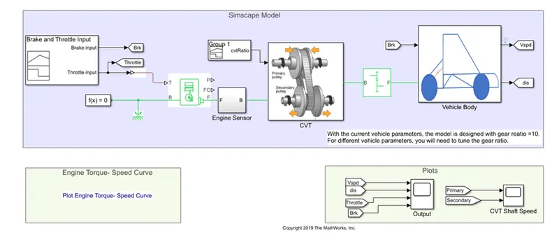
CVT MODEL: It contains Simscape model of BAJA ATV with CVT
Input for generic engine
Engine Torque-Speed Curve
Engine RPM
Input for CVT
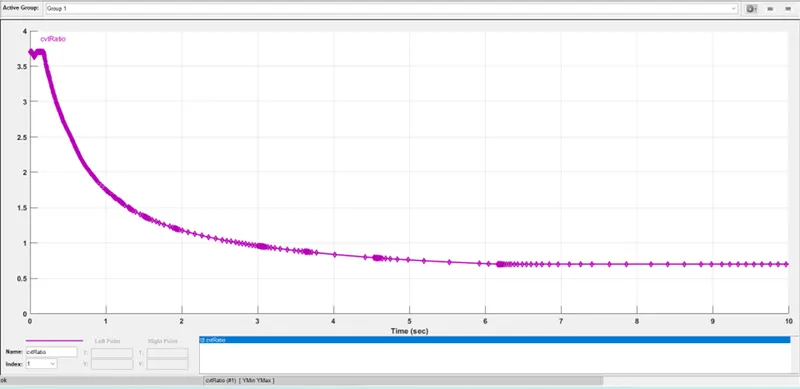
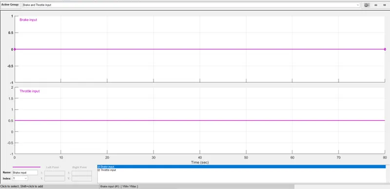
- Here in this model the throttle and brake inputs are given using a signal builder block.
- Here in this model throttle input is 0.5 and brake input is 0.
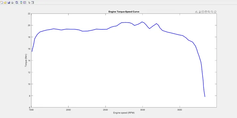
- In this model we have used the generic engine block. The generic engine uses a programmed relationship between speed and torque modulated by the throttle signal.
- The throttle signal 0.5 was given to port T and the speed torque data points are extracted from the “ENGINE TORQUE SPEED CURVE” using the GRABIT option.
- Crank shaft port F is connected to an engine sensor.
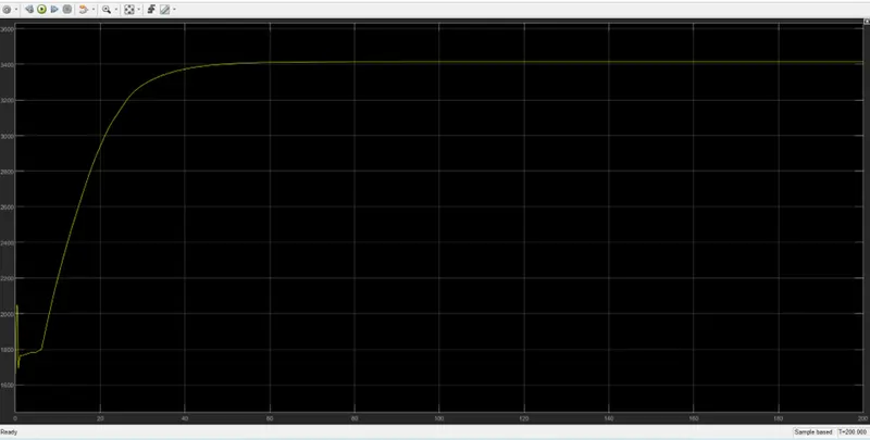
- In the Engine sensor RPM sensor has been used to measure the Engine RPM.
- The crank shaft angular velocity has been given as an input to primary pulley of the CVT from the Engine sensor.
- CVT ratio has been given to the CVT with the help of signal builder block.
- CVT secondary pulley is connected to the simple gear with gear ratio equal to 10.
- From the simple gear signal has been given to vehicle body.
- Vehicle body consists of body mass aerodynamic drag, road incline and weight distribution between axles due to the acceleration and road profile.
- The double shoe brake in the vehicle body is to apply brakes to the rear wheels.
OUTPUT:
CVT Shaft Speed
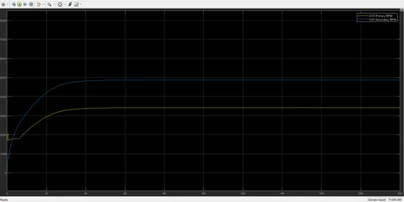
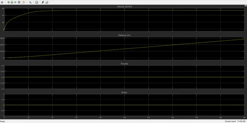
- From the scope block we can observe the velocity and distance of the vehicle body for the given throttle and brake inputs. We can also observe the CVT shaft speed of primary and shaft pulley for the given CVT ratio.
- Here we can see that the secondary pulley rpm is greater than the primary pulley because when we accelerate the primary pulley will expand and secondary pulley will contract this process is nothing but speed reduction.
CASE-1(b):
CVT MODEL WITH DASBOARD: It contains Simscape model of BAJA ATV with CVT with dashboard.
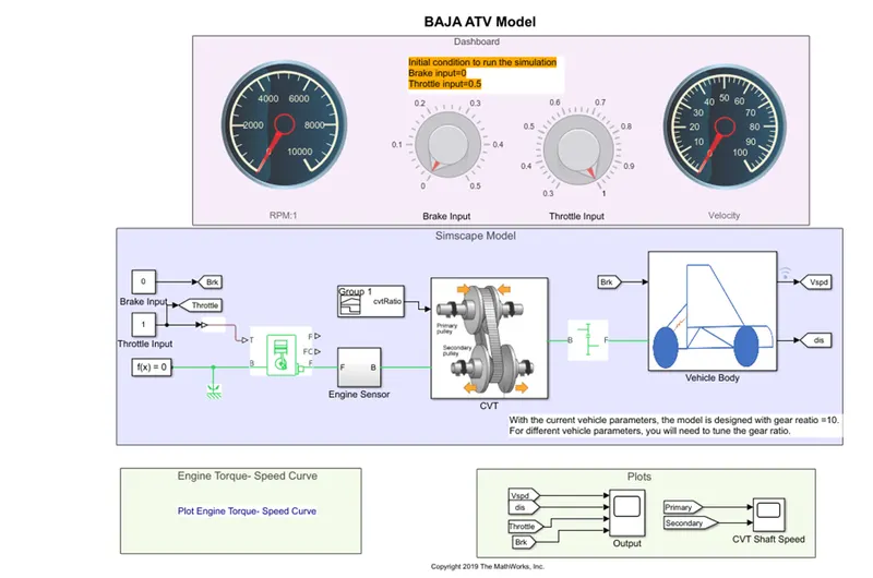
- This model is same as BAJA ATV with CVT model but we created it using Dashboard blocks.
- Here in this model the throttle and brake inputs are given using a constant block.
- Here in this model throttle input and brake input can be varied through a knob.
- Velocity of the vehicle and Engine RPM can be observed through the gauge.
OUTPUT:
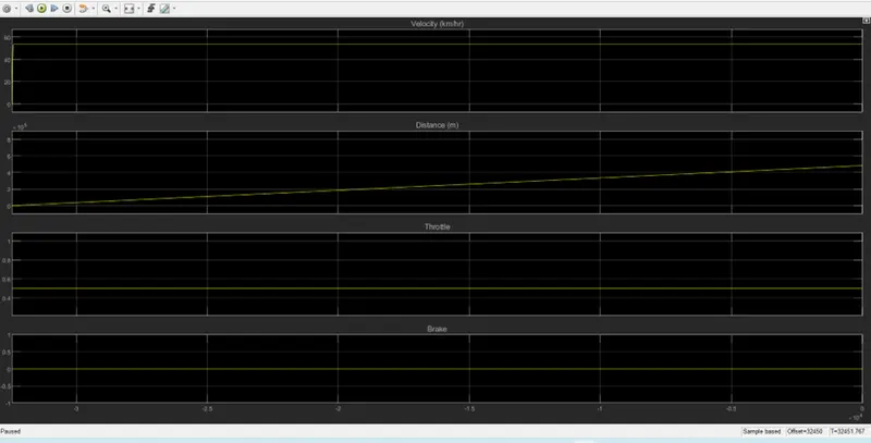
CVT Shaft Speed
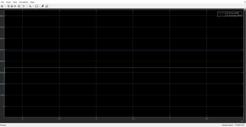
- From the scope block we can observe the velocity and distance of the vehicle body for the given throttle and brake inputs. We can also observe the CVT shaft speed of primary and shaft pulley for the given CVT ratio.
- Here we can see that the secondary pulley rpm is greater than the primary pulley because when we accelerate the primary pulley will expand and secondary pulley will contract this process is nothing but speed reduction.
CASE-2(a):
CVT MODEL WITH LOOKUP TABLE: It contains Simscape model of BAJA ATV with CVT with LOOKUP TABLE.
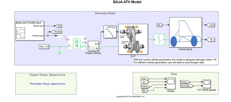
- This model is same as BAJA ATV with CVT model but we given the CVT ratio by using LOOKUP TABLE.
- Here in this model the throttle and brake inputs are given using a signal builder block. As throttle input is 1 and brake input is 0.
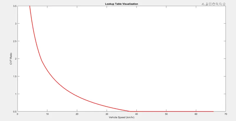
- Here in this model CVT ratio is given through 1-D lookup table where speed and CVT ratio data are feeded from Lt_cvtratio_rpm.mat file
OUTPUT:
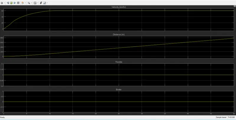
CVT Shaft Speed
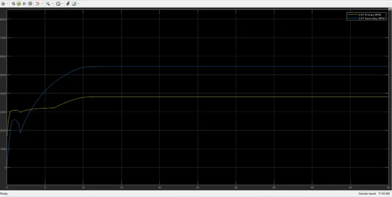
- From the scope block we can observe the velocity and distance of the vehicle body for the given throttle and brake inputs. We can also observe the CVT shaft speed of primary and shaft pulley for the given CVT ratio.
- Here we can see that the secondary pulley rpm is greater than the primary pulley because when we accelerate the primary pulley will expand and secondary pulley will contract this process is nothing but speed reduction.
CASE-2(b):
CVT MODEL DATA EXTRACTION: It contains Simscape model of BAJA ATV with CVT.
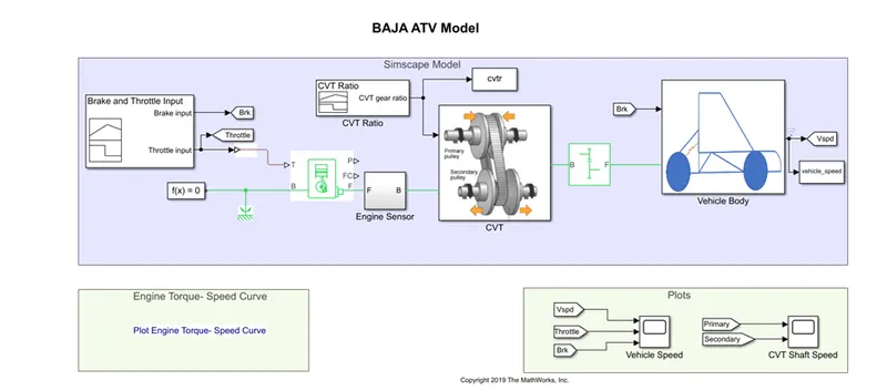
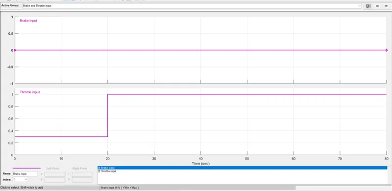
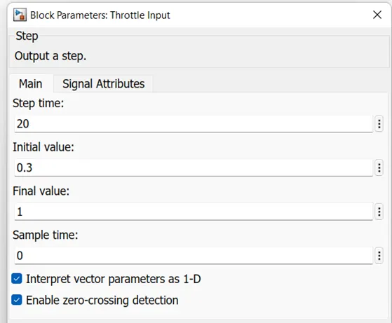
- This model is same as BAJA ATV with CVT model. But in this model throttle input is 0.3 up to 20secs, it will change to 1 for remaining time and brake input is 0.
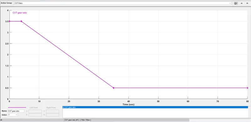
- CVT gear ratio has been given through signal builder.
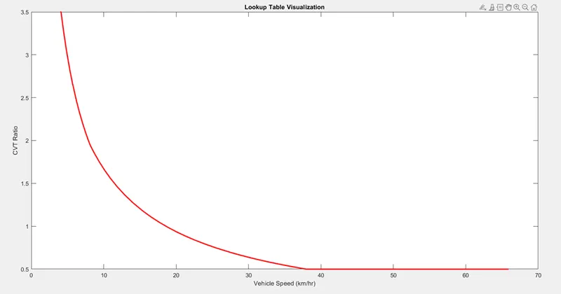
- Here in this model, we have used the two-work space block to extract the lookup table visualisation of CVT gear ratio with respect to vehicle speed.
CVT Gear Ratio
- Code to extract the lookup table visualisation:
%% Load and simulate the model
cvtModel_data
sim('cvtModel_data')
%% Visualize the lookup table
plot(vehicle_speed,cvtr,'r','LineWidth',2)
xlabel ('Vehicle Speed (km/hr)')
ylabel ('CVT Ratio')
title ('Lookup Table Visualization')
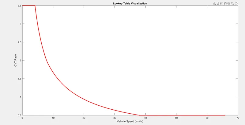
OUTPUT:
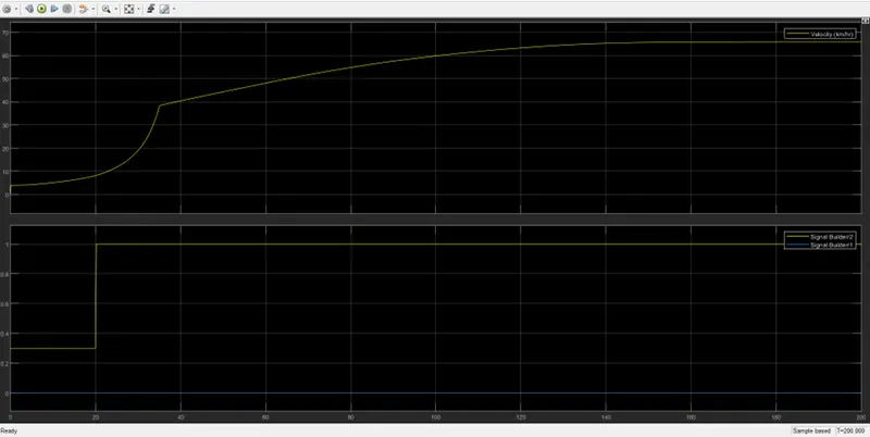
CVT Shaft Speed
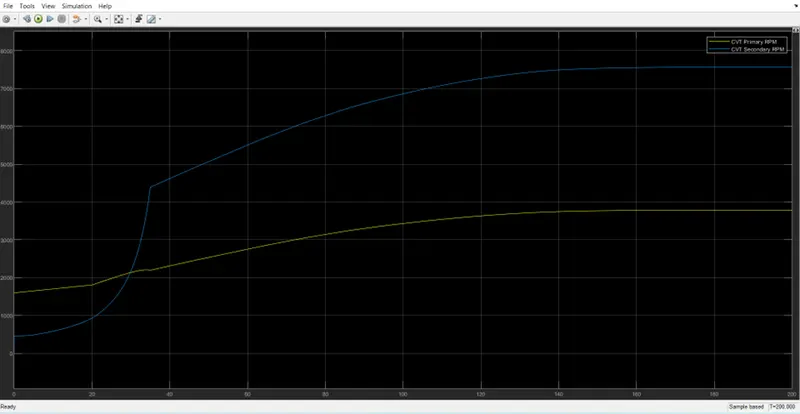
- From the scope block we can observe the velocity and distance of the vehicle body for the given throttle and brake inputs. We can also observe the CVT shaft speed of primary and shaft pulley for the given CVT ratio.
- Here we can see that secondary pulley rpm is less than the primary pulley till 30sec because the throttle input is less i.e., 0.3 but after 30 the throttle input has been increased to 1 then the secondary pulley rpm will be greater than the primary pulley rpm.
CASE-2(c):
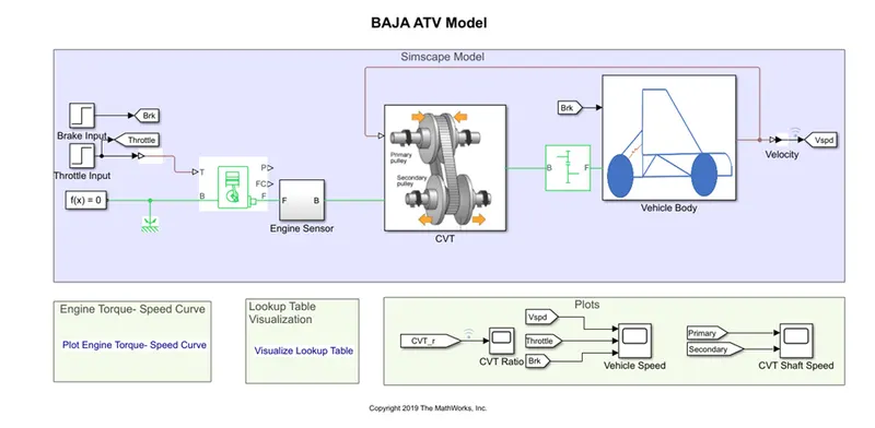
MAPPED CVT MODEL: It contains Simscape model of BAJA ATV with CVT.
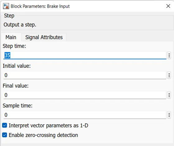
Brake Input Parameters (Step Input)
Throttle Input Parameters (Step Input)
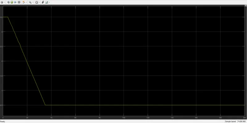
Input for CVT Ratio
Lookup Table Visualization
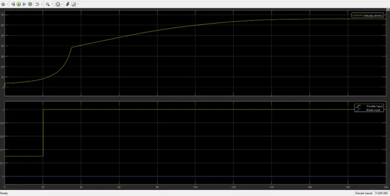
- This model is same as BAJA ATV with CVT model. But in this model throttle and brake input are given as step input.
- CVT gear ratio has been given through lookup table.
- It is a closed loop model with velocity of a vehicle as feed back to the CVT.
OUTPUT:
CVT Shaft Speed
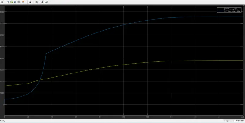
- From the scope block we can observe the velocity and distance of the vehicle body for the given throttle and brake inputs. We can also observe the CVT shaft speed of primary and shaft pulley for the given CVT ratio.
- Here we can see that secondary pulley rpm is less than the primary pulley till 20sec because the throttle input is less i.e., 0.3 but after 20 the throttle input has been increased to 1 then the secondary pulley rpm will be greater than the primary pulley rpm.
CASE-2 (d):
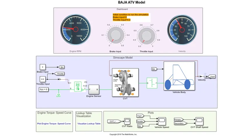
MAPPED CVT MODEL WITH DASHBOARD: It contains Simscape model of BAJA ATV with CVT with dashboard.
Input for CVT Ratio
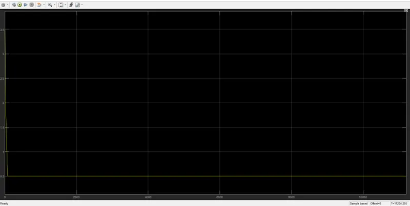
Lookup Table Visualization
- This model is same as BAJA ATV with mapped CVT model but we created it using Dashboard blocks.
- Here in this model the throttle and brake inputs are given using a constant block.
- Here in this model throttle input and brake input can be varied through a knob.
- Velocity of the vehicle and Engine RPM can be observed through the gauge.
OUTPUT:
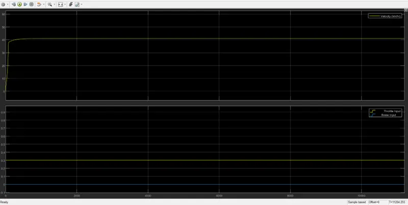
CVT Shaft Speed
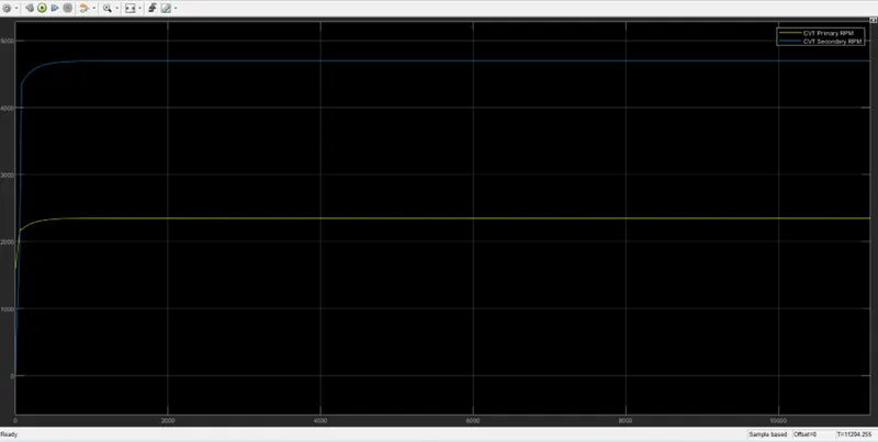
- From the scope block we can observe the velocity and distance of the vehicle body for the given throttle and brake inputs. We can also observe the CVT shaft speed of primary and shaft pulley for the given CVT ratio.
- Here we can see that the secondary pulley rpm is greater than the primary pulley because when we accelerate the primary pulley will expand and secondary pulley will contract this process is nothing but speed reduction.
CONCLUSION:
We can conclude that we have successfully simulated the BAJA ALL TERRAIN VEHICLE with different inputs and CVT ratio.