Week-7 Challenge: DC Motor Control
EV 17 TH LIVE BATCH
2.Que:
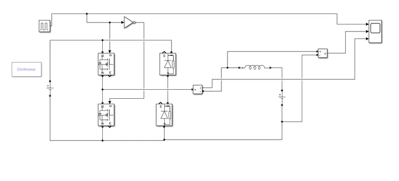
- To start with the two-quadrant chopper drive,we have first given the input from the dc source voltage. The voltage value is kept to be 32v.
- For power switches or transistors, we will be using the MOSFET coupled with the diode in parallel. There will be two pairs of these switches and diode so that we can operate the model in 2-quadrant and all these are connected accordingly.
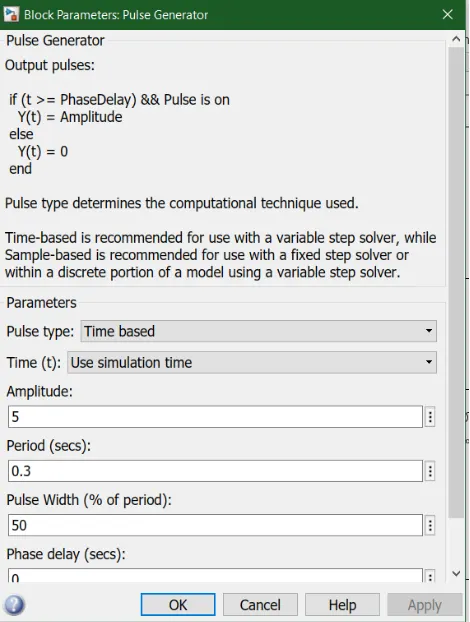
- Now the pulse generator with 50% duty cycle,0.3 sec, and 5 as an amplitude. The output of the generator is connected to the NOT operator which ensures that only one switch is working at a time. Then it is further connected to the gate of the switches.
- The inductor is provided which will store the current when switch 1 is turned off. Then for the load, we have used another dc source with a voltage 16v as shown in below diagram.
- To measure current and voltage the measuring block is used whose output can be visualized using the scope.
- we need powergui block to simulate any simulink model containing simscape electrical specialized power systems blocks.it stores the equivalent simulink circuit that represent the state space equation of the model.
working:
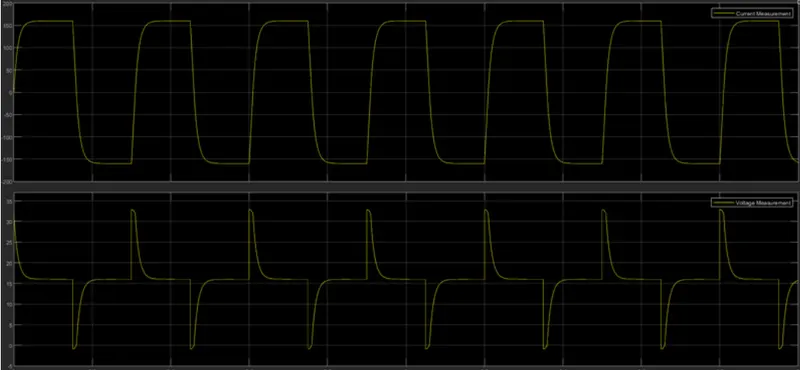
- In a two-quadrant chopper, the average voltage will be always positive but average load current might be positive or negative. The two switches CH1 and CH2 should not be turned on simultaneously as the combined action may cause a short circuit in supply lines.
- when the chopper CH1 is on, the current flows from the source to load the inductor stores energy. The current flow from MOSFET1 to the inductor to load means the voltage and current are flowing from source to load.
- when CH1 turns off, the freewheeling diode starts conducting and the output voltage will be equal to v. The direction of load current will be reversed since the inductor is now discharging itself and current will be flowing towards the source.
- for the regenerative braking, the load current will be negative when CH2 is on. The current complete its path from the mosfet2 to the negative terminal of load diode to diode2.
3.Que:
Brief about the BLDC motor:
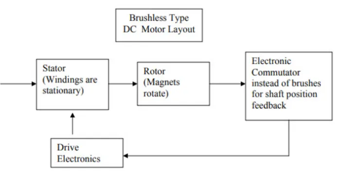
It often helps to explain how a brushed DC motor works first, as they were used for some time before brushless DC motors were available. A brushed DC motor has permanent magnet on the outside of its structure, with a spinning armature on the inside.The permanent magnet, which are stationary on the outside, are called the stator. The armature which rotates and contain an electromagnet is called the rotor. In a brushed DC motor, the rotor spins 180-degrees when an electric current is run to the armature. To go any further the poles of electromagnet must flip. The brushes as the rotor spins, make contact with stator, flipping magnetic field and allowing the rotor to spin a full 360-degrees.
A brushless DC motor is essentially flipped inside out, eliminating the need for brushed to flip the electromagnetic field. In brushless DC motors, the permanent magnets are on rotor, and electromagnet are on the stator. A computer then charges electromagnet in the stator to rotate the rotor a full 360-degrees.
Construction of BLDC motor-
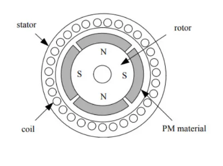
The main design difference between brushed and brushless motors is the replacement of a mechanical commutator with an electric switch circuit. keeping that in mind, a BLDC motor is a type of synchronous motor in the sense that the magnetic field generated by the stator and the rotor revolves at the same frequency. Brushless motors are available in three configuration: single-phase, two-phase, and three-phase BLDC is the most common one. The following image shows the cross-section of a BLDC motor.
Stator
The structure of the stator of a BLDC motor is similar to that of an induction motor. it is made up of stacked steel laminations with axially cut slots for winding. The winding in BLDC are slightly different than that of the traditional inductor motor.
Rotor
The rotor part of BLDC motor is made up of permanent magnets(usually, rare earth alloy magnets like neodymium,samarium cobalt and alloy of neodymium,ferrite and boron(NdFeB)).
working principle
consider the following setup of three winding in stator designated A,B and C. for the sake of understanding, let us replace rotor with a single magnet.we know taht when a current is applied through a coil, a magnetic field is generated and the orientation of the field lines. the poles of the generated magnet will depend on the direction of the current flowing through the coil. using the principle, if we supply current to the coil A so that it will generate a magnetic field and attract the rotor magnet. The position of rotor magnet will shift slightly clockwise and will align with A.
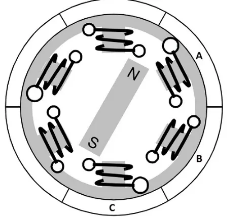
If we now pass current through coils B and C one after the other the rotor magnet will rotate in clockwise direction.To increase efficiency we can wind the opposite coils using a single coil so that we get double attraction. further increasing efficiency, we can energize two coils ata the same time so that one coil will attract magnet and other coil will repel it. during this time, the rapid will be idle.
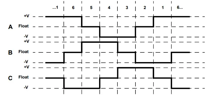
for a complete 360 degree rotation of the rotor magnet, six possible combination of the coils A,B,C are applicable and are shown in the following timing diagram. Base on the above diagram we can confirm that at any time, one phase is positive one phase is negative and third phase is idle. so based on the input from the Hall sensors we have two switch the phases as per the above diagram.