Project
AIM: To carry out a system-level simulation of an all-terrain vahicle using simulink.
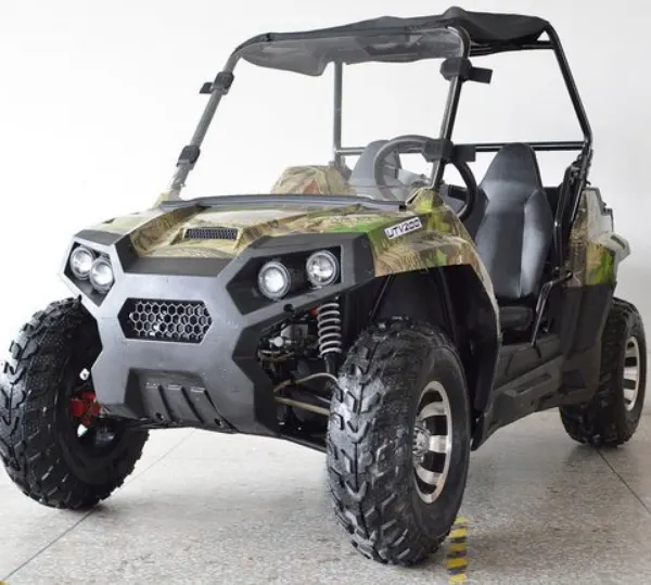
ALL TERRAIN VEHICLE:
An all-terrain vehicle (ATV) is defined as a motorized off-highway vehicle designed to travel on four low-prerssure or non-pneumatic tires, having a seat designed to be straddled by the operator and handlebars for steering control.
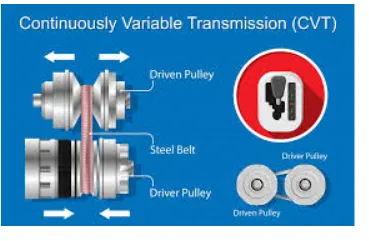
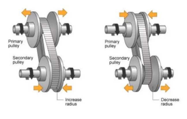
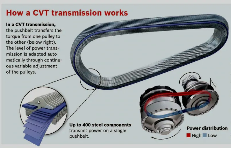
CVT: A CVT or continuously variable transmisssion is an automatic, single-speed, and gearless transmission that can shift through an infinite number of gear ratios. A continuously variable transmission (CVT) is a transmission that operate on an ingenious pulley system that automatically varies the transmission ratio,allowing an infinte variability between highest and lowest gears with no discrete steps or shifts. CVTs provide more usable power,better fuel economy and smoother driving experience than traditional transmission that use gearboxes with fixed numbers of gear sets.
SOLUTION:
Part*1:BAJA ATV Model without Lookup Table
1.1 Without Dashboard
A simulink model for the BAJA ATV Model is shown below.
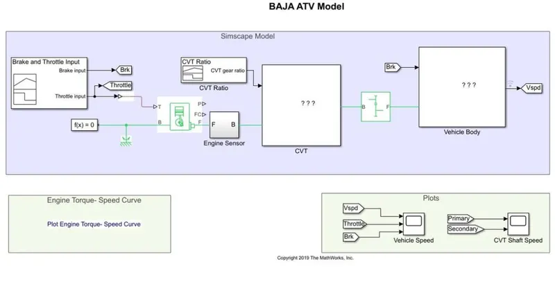
The models consist of common blocks as follows:
signal Builder:
The signal Builder block allows you to create interchangeable groups of piecewise linear signal source and use them in a model. you can quickly switch the signal groups into and out of a model to facilitate testing.
Genewric Engine:
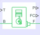
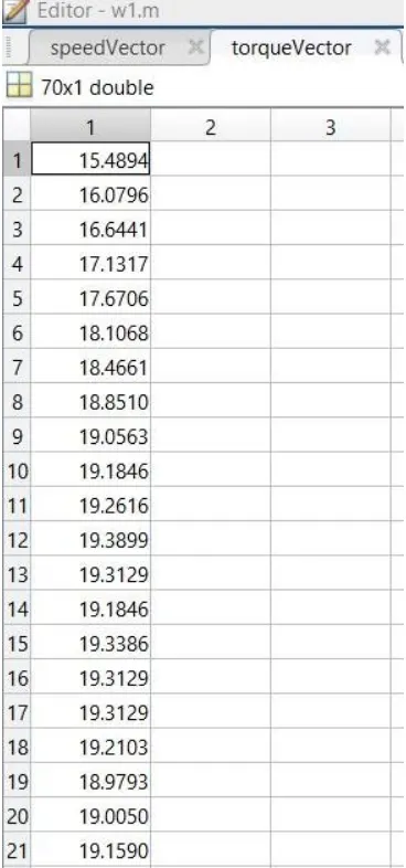
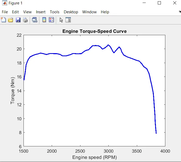
Represent a systemlevel model of spark-ignition and diesel engines suitable for use at initial stages of modeling when only the basic parameter are available. connection F and B mechanical rotational conserving parts associated with the engine crankshaft and engine block,respectively. connections P and FC are physical signal output part through which engine power and fuel consumption rate are reported. speed vector and torque vector are the assigned parameter.
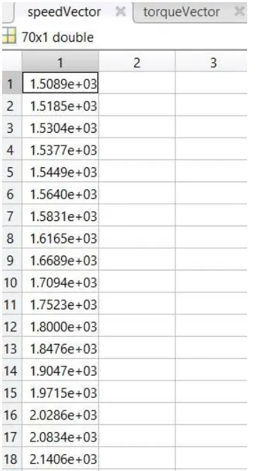
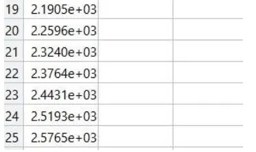
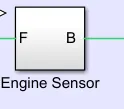
Engine Sensor:
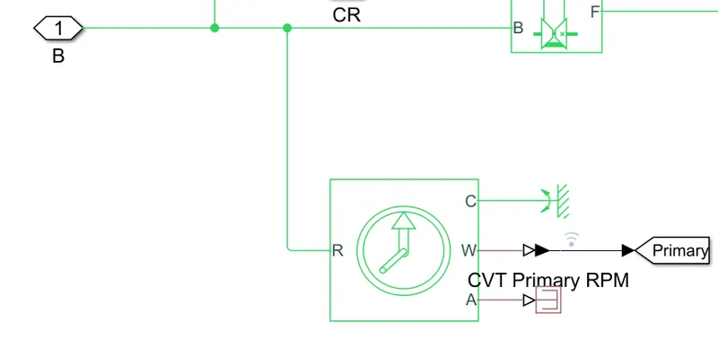
Ideal Rotational Motion Sensor: The block reprsent an ideal mechanical rotational motion sensor, that is, a device that converts an across variable measured between two mechanical rotational nodes into a control signal proportional to angular velocity or angle. The sensor is ideal since it does not account for inertia, friction, delays, energy consumption, ansd so on.connections R and C are mechanical rotational conserving ports and connection W and A are physical signal output ports for velocity and angular displacement, respectively.
Simple Gear:

Represents a fixed-ratio gear or gearbox. no inertia or compliance is modeled in this block. you can optionally include gear meshing and viscous bearing losses. connections B (base) and F (follower) are mechanical rotational conserving port. specify the relation between base and follwer rotation directions with the output shaft rotates parameter. optionally include thermal effects and expose thermal conserving port H by right-clicking on the block and selecting simscape block choices to switch between variants. Follower (F) to base (B) teeth ratio (NF/NB):4
CVT Subsystem:
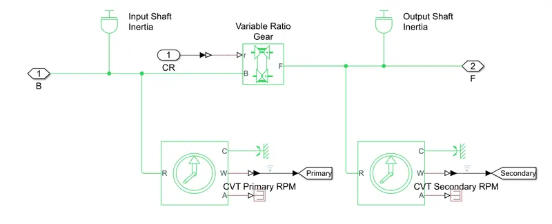
The CVT subsystem consist of the following blocks:
Inertia:
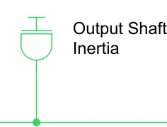
The block represents an ideal mechanical rotational inertia. The block has one mechanical rotational conserving port.The block positive direction is from its port to the reference point. This means that the inertia torque is positive if the inertia is accelerated in a positive direction.
Variable Ratio Transmission:
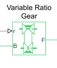
Represent a variable ratio gearbox such as implemented by mechanical belt CVT, electric, or hydraulic transmissions. The physical signal input r defines the ratio of input to output angular shaft velocities. connection B (base) and F (follower) are mechanical rotational conserving ports. specify the relation between base and follower rotation directions with the output shaft rotates parameter.
Vehicle Body Subsystem:
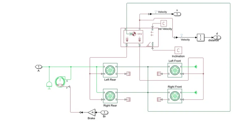
Vehicle Body:
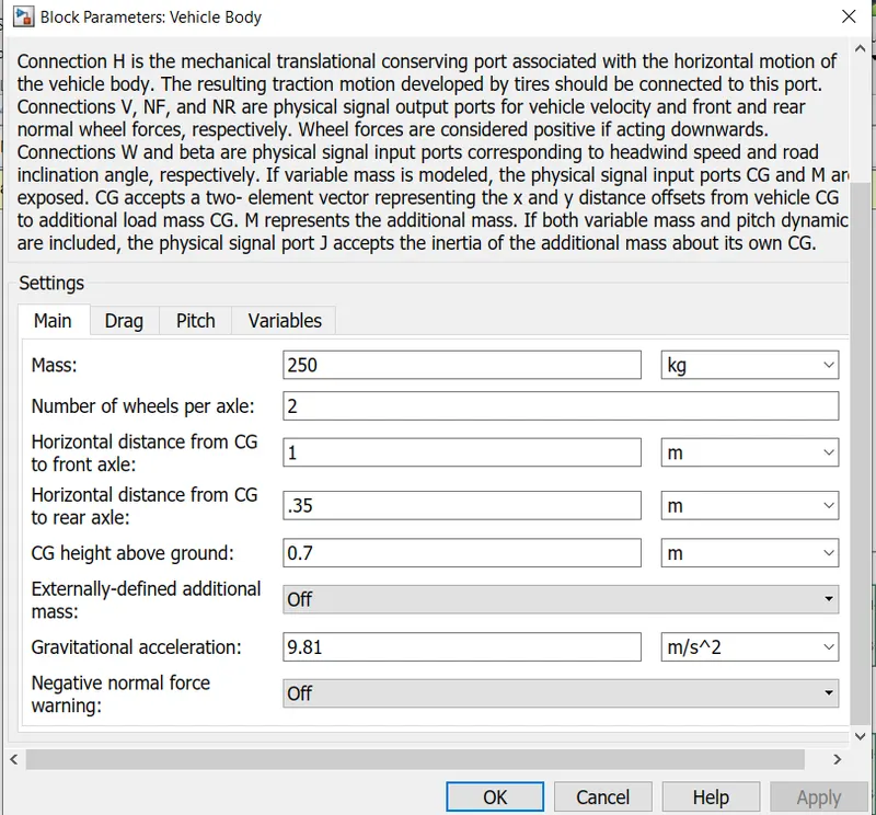
Represents a two-axle vehicle body on longitudinal motion. The block accounts for body mass, aerodynamic drags, road incline, and weight distribution between axle due to acceleration and road profile. The vehicle can have the same or a different number of wheels on each axle. optionally include pitch and suspension dynamics or additional variable mass and inertia. The vehicle does not move vertically relative to the ground. connection H is the mechanical translational conserving port associated with the horizontal motion of the vehicle body. The resulting traction motion developed by tires should be connected to this port. connections V, NF and NR are physical signal output ports for vehicle velocity and front and rear normal wheel forces, respectively. wheel forces are considered positive if acting downwards. connections W and beta are physical signal input port corresponding to headwind speed and road inclination angle, respectively. if the variable mass is modeled, the physical signal input ports CG and M are exposed. CG accepts a two-element vector representing the x and y distance offset from vehicle CG to additional load mass CG. M represents the additional mass. if both variable mass and pitch dynamics are included, the physical signal port J accepts the inertia of the additional mass about its own CG.
Parameter are:
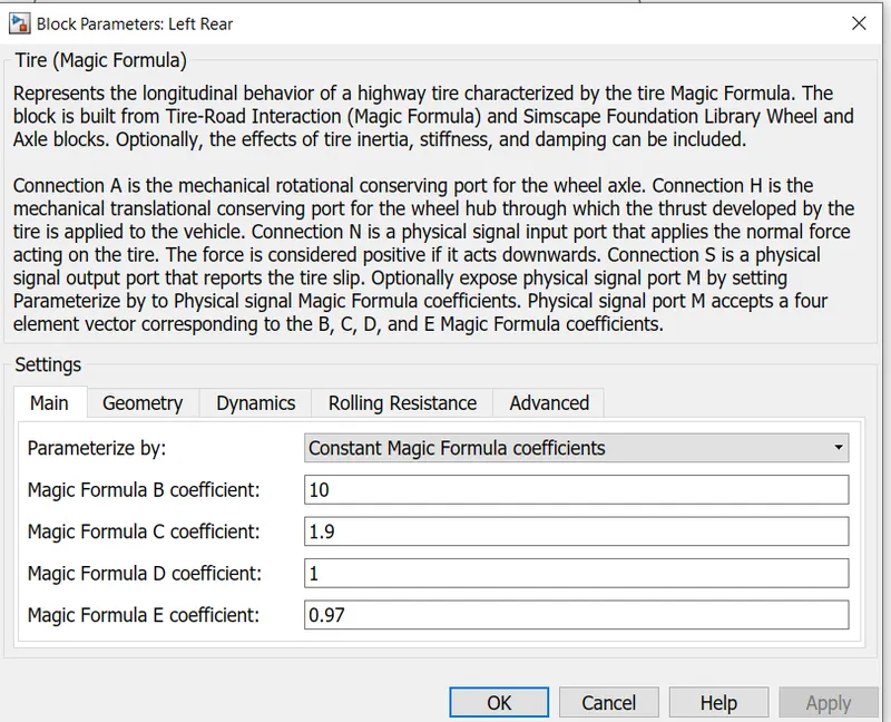
Tire:
Represents the longitudinal behavior of a highway tire characterized by the tire magic formula. The block is built from Tire-Road interaction (magic formula) and simscape foundation library wheel and axle blocks. optionally, the effects of tire inertia, stiffness, and damping can be included. connection A is the mechanical rotational conserving port for the wheel axle. connection H is the mechanical translational conserving port for the wheel hub through which the thrust developed by the tire is applied to the vehicle. connection N is a physical signal input port that applies the normal force acting on the tire. The force is considered positive if it acts downwards. connection S is a physical signal output port that reports the tire slip. optionally expose physical signal port M by setting parameterize by to physical signal magic formula coefficients. physical signal port M accepts a four-element vector corresponding to the B, C, D, and E magic formula coefficients.
Parameter (common for all tires) are:
Double-Shoe Brake:
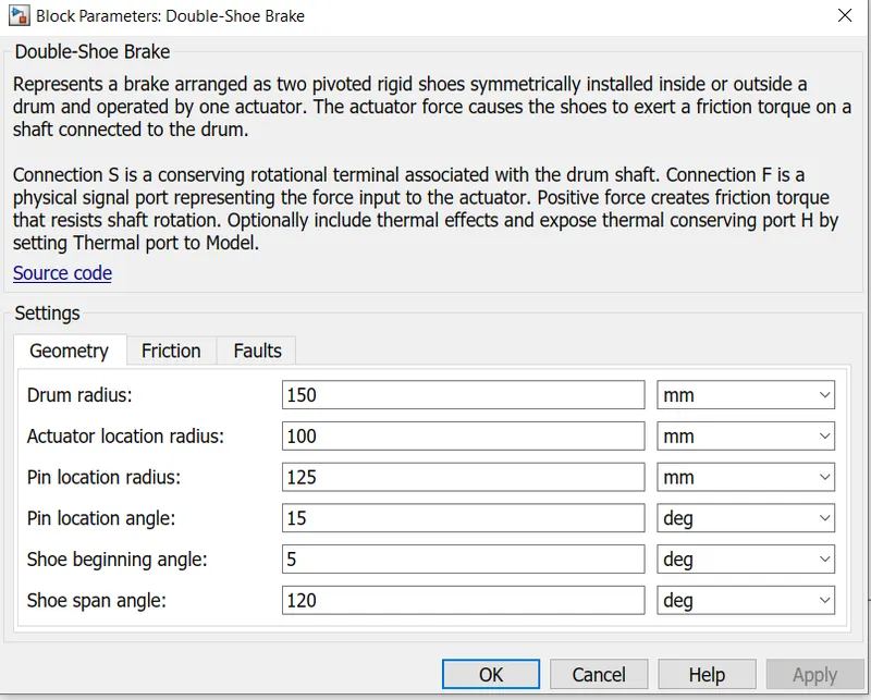
Represents a brake arranged as two pivoted rigid shoes symmetrically installed inside or outside a drum and operated by one actuator. The actuator force causes the shoes to exert a friction torque on a shaft conncted to the drum. connection s is a conserving rotational terminal associated with the drum shaft. connection F is a physical signal port representing the force input to the actuator. positive force creates friction torque that resists shaft rotation. optionally include thermal effects and expose thermal conserving port H by setting thermal port to model.
Parameter are:
Torque vs speed characteristics:
Input 1.1:
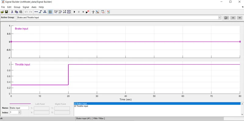
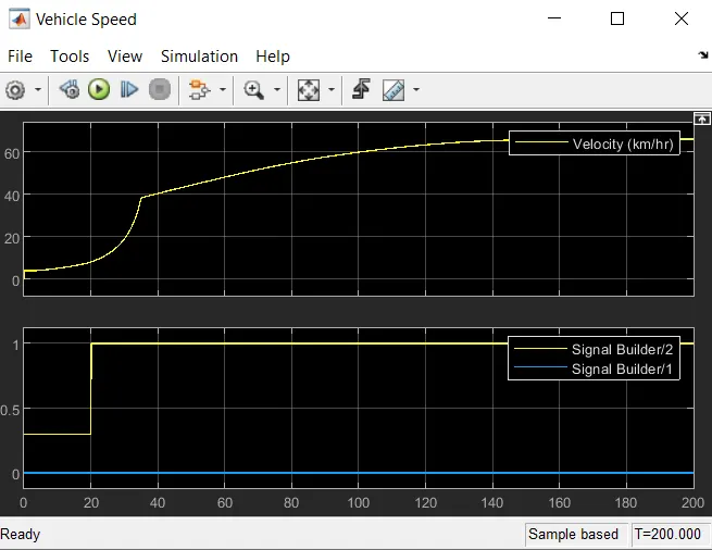
Brake and Throttle input:
Brake input is constant i.e zero throughout the time of 80 sec. Throttle input is 0.3 for first 20 sec, accelerates to 1 at the same and remains constant throughout the remaining time till 80 sec.
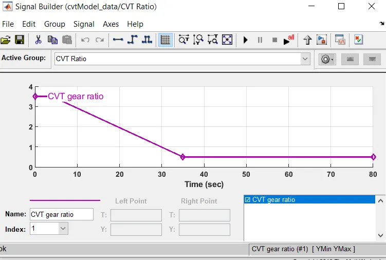
CVT Ratio:
The CVT gear ratio 3.5 for the first 4 secs, then drops down to 5 till 35 secs and remains constant there after till 80 sec.
Output 1.1:
Velocity:
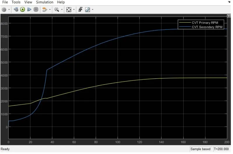
CVT Shaft speed:
1.2 with Dashboard
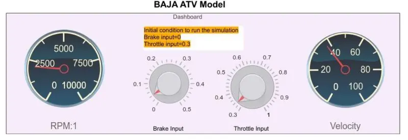
A simulink model for the BAJA ATV Model including the dashboard is shown below.
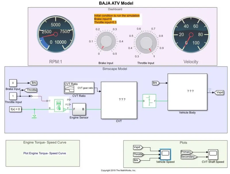
The rest of the parts and subsystems are common in the above part 1.1.
Dashboard: A dashboard( also callled dash, instrument panel(IP), or fascia) is a control panel usually located directly ahead of a vehicle's driver, displaying instrumentation and controls for the vehicle's operation. In this model a dashboard is used to control the inputs-'Throttle' &'Brake' with knobs.
Output 2.2:
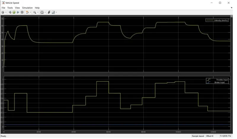
velocity
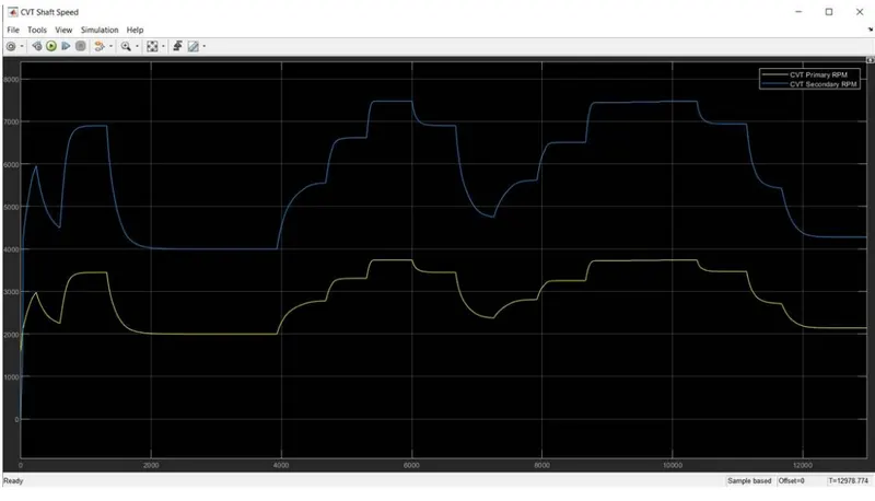
CVT Shaft speed:
CONCLUSION:
Hence, the given BAJA ATV Model was simulated successfully and from the above results, we can infer that:
-Velocity, CVT shaft speed and Engine speed are directly proportional to the Throttle input and inversely proportional to the Brake input.
-CVT Primary speed is greater than CVT secondary speed as they are directly proportinal to their shaft diameter.
-The variation in vehicle velocity can be observed with change in throttle and brake inputs.
-With increase in braking value, the speed of vehicle decreases. on the other hand, increasing thr throttle leads to increased vehicle velocity.